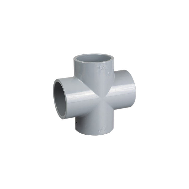
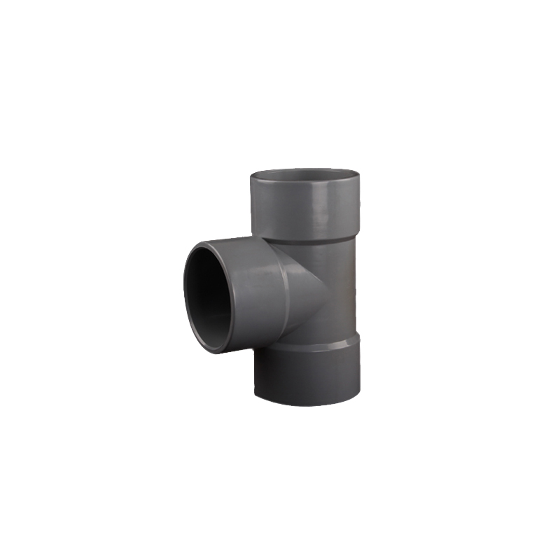
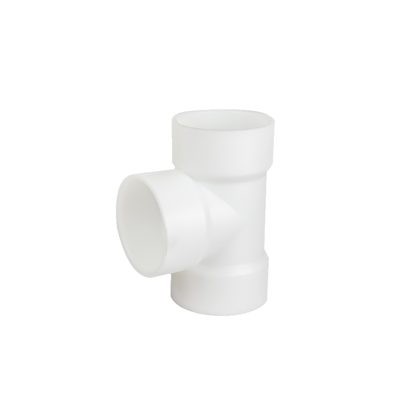
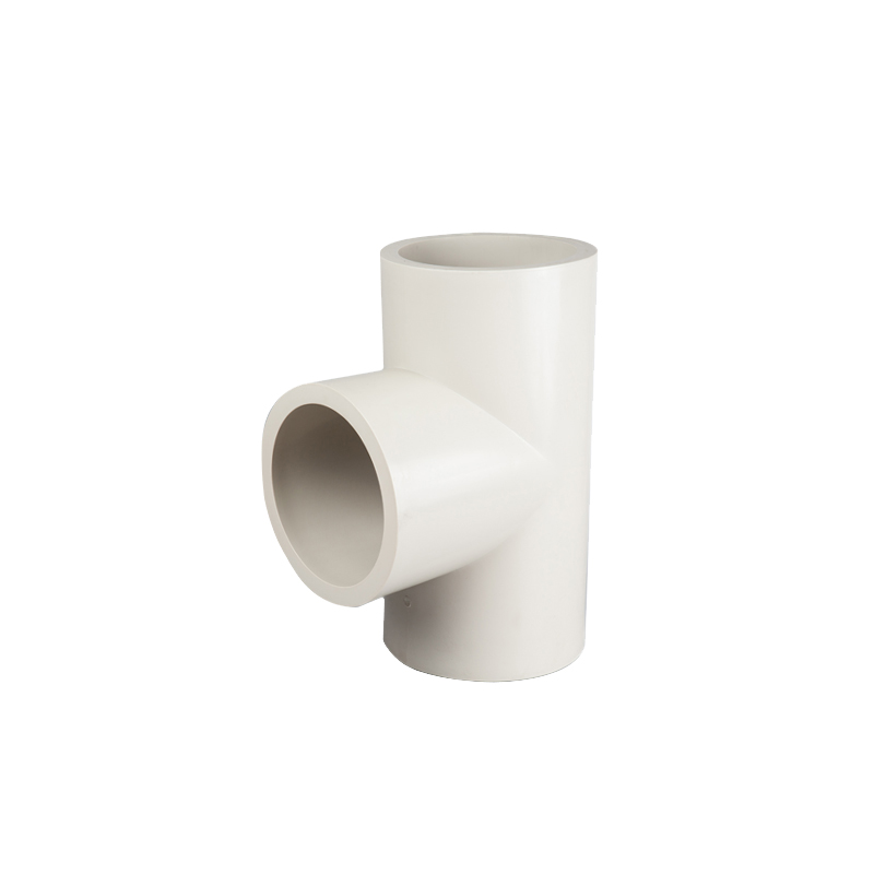
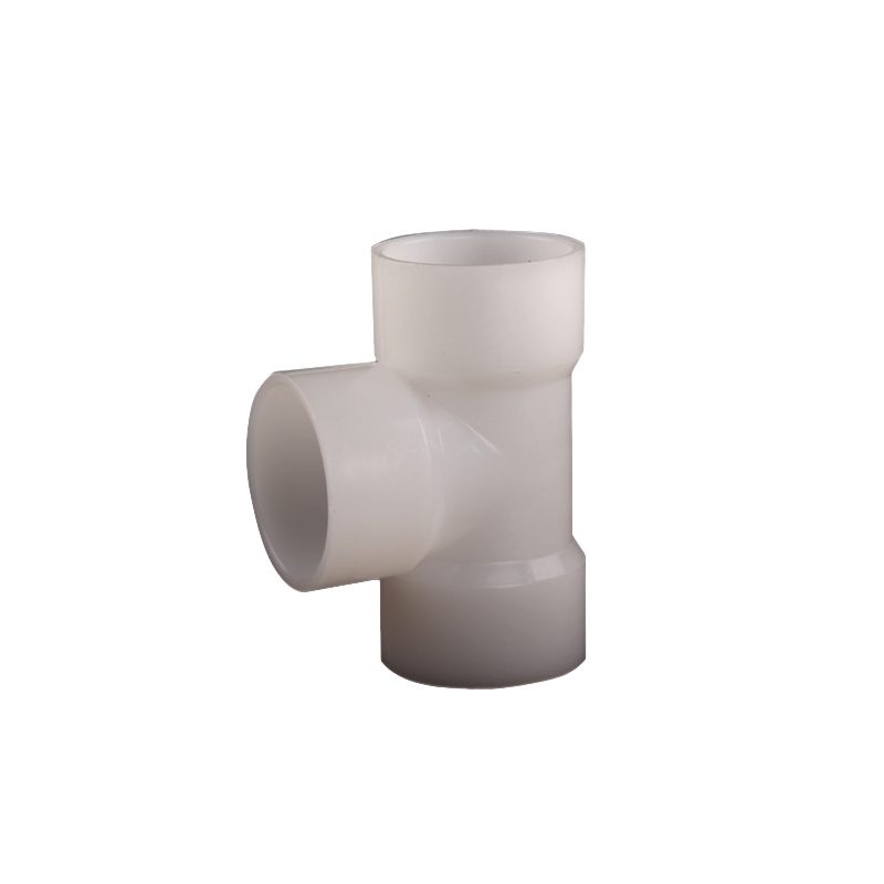
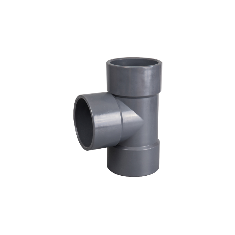
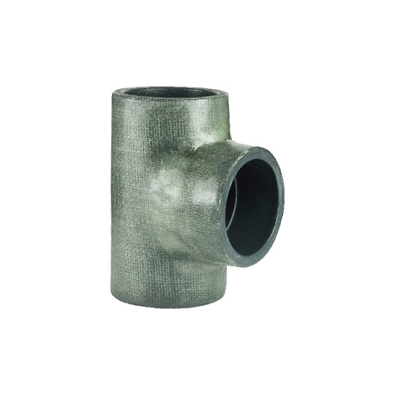
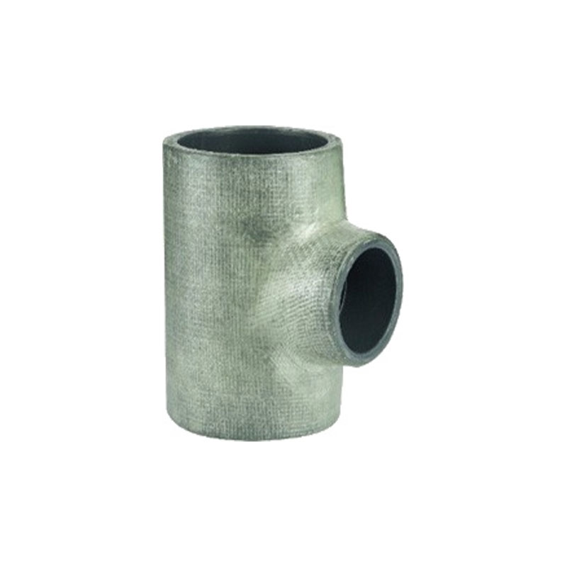
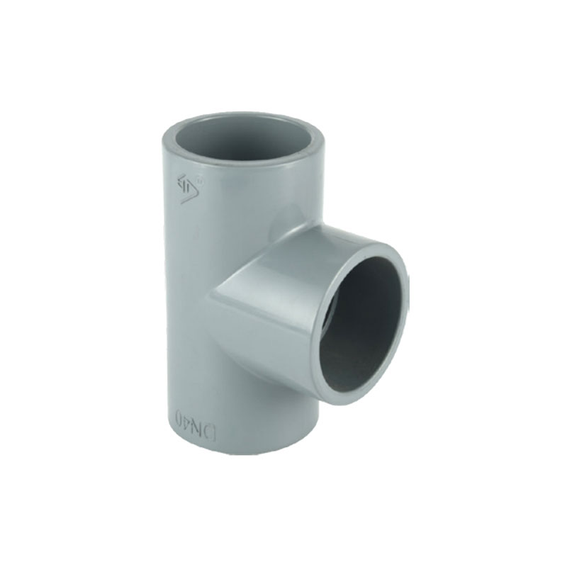
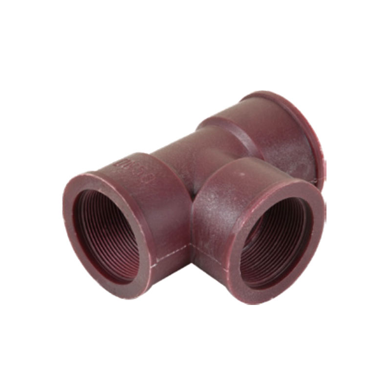
A Plastic Pipe Fitting Tee divides flow between a straight-through main run and a 90° branch outlet. The engineering challenge in specifying and installing tees is rarely the fitting itself — it is ensuring predictable, correctly balanced flow distribution across every branch in a system, which requires understanding how the split actually occurs rather than assuming the fitting's symmetric appearance guarantees a symmetric flow result.
Ningbo Baodi Plastic Valve Co., Ltd. has supplied plastic piping fittings alongside its broader valve product range since expanding into industrial plastic pipes and fittings in 2006, with tees widely used across water treatment distribution headers, chemical transfer manifolds and process branch lines for the company's export clients across multiple industries.
Flow Split Mechanism
Flow entering a tee divides according to the relative resistance of each downstream path — pipe length, fittings, valves and connected equipment — not according to the tee's own geometry. Two branches identical in nominal size can deliver unequal flow if one has more downstream fittings, a longer run, or a partially closed valve. This is a fundamental hydraulic principle that applies regardless of how carefully the tee itself was manufactured or how symmetric its physical dimensions are: the fitting establishes the connection point, but the actual flow split is governed entirely by what happens downstream of that point on each branch.
In headers with multiple tees along their length, branches closer to the supply source can receive disproportionately more flow than branches further downstream unless this is specifically addressed in the design, because the branches nearer the source generally experience a smaller pressure drop to reach that point than branches located further along the header, where the fluid has already lost some pressure traveling through the upstream portion of the main run and through any tees it passed on the way. This effect becomes more pronounced as the number of branches along a single header increases and as the header's own length grows relative to its diameter.
Branch Turbulence Characteristics
The branch outlet of a tee experiences greater turbulence than the straight-through main run, because flow must change direction to exit through the branch port, in a manner analogous to the flow-separation behavior discussed in relation to elbow fittings, though the three-way geometry of a tee introduces additional complexity beyond a simple two-port elbow. This localized effect is independent of the header-wide flow-balancing consideration above and is one reason branch connections are more prone to pressure loss than the main run passing through the same fitting — a flow path continuing straight through a tee experiences meaningfully less disturbance than a flow path exiting through the branch.
This distinction matters when sizing branch-mounted equipment such as flow meters or control valves: a device mounted close to the tee's branch outlet may experience a more disturbed inlet flow profile than an equivalent device mounted on the main run at the same nominal distance from the fitting, and straight-run allowances for branch-mounted instrumentation should generally be treated with at least as much caution as those for elbow-adjacent instrumentation, if not more.
Straight Tee vs Reducing Tee
|
Straight (Equal) Tee |
Reducing Tee |
| Branch size vs main run |
Same size |
Branch smaller than main run |
| Typical application |
Symmetric branch lines, balanced distribution headers |
Instrument taps, smaller dosing or sampling lines |
Where a branch serves a significantly smaller flow requirement than the main run, a reducing tee avoids oversizing that branch and its downstream components — an instrument tap or sampling connection rarely needs to match the main header's diameter, and specifying a full-size branch in these cases adds unnecessary material cost without any corresponding functional benefit. The specific engineering considerations that apply to reducing tees, including their three-dimension sizing requirements and their role in header economics, are addressed separately and in greater depth in the reducing tee product category.
Manifold and Distribution Header Design
Multiple tees along a common header create a distribution manifold supplying parallel process lines, filtration trains or dosing points — a configuration common across water treatment plants, where a single main feed line must supply several parallel treatment trains, each requiring a metered and controllable flow share of the total. Balancing valves on each branch are the standard method for correcting the uneven-flow tendency described above, since perfectly matched branch resistance is rarely achievable through pipe sizing alone; even a header designed with identical branch pipe lengths and identical downstream equipment can develop unequal flow distribution over time as individual branches accumulate different amounts of fouling, scale, or valve wear.
Branch spacing and sizing should be planned with this imbalance tendency in mind, particularly on longer headers with multiple take-off points, where the cumulative pressure drop along the main run between the first and last branch can become a significant fraction of the total available pressure, exaggerating the flow-imbalance effect at branches furthest from the source. Some header designs address this directly by progressively reducing the main run diameter as it moves away from the source and flow is progressively drawn off at each branch, which helps maintain a more consistent velocity — and correspondingly more consistent pressure drop per unit length — along the full header rather than allowing velocity to drop steadily as flow is removed at each successive branch.
Orientation Specification
Branch orientation should be determined at the header design stage rather than left to installation convenience. An upward-facing branch outlet can trap air, which over time can accumulate into a pocket large enough to disrupt flow at that branch or, in extreme cases, to cause an air-lock condition that effectively blocks flow through the branch entirely until the trapped air is released. A downward-facing outlet may accumulate sediment in some fluid services, particularly where the main flow velocity is not high enough to keep particulates fully in suspension as they pass the branch connection.
Correct orientation depends on the fluid handled and whether deliberate air-release or drainage behavior is required at that connection — a header carrying treated water with negligible particulate content has different orientation priorities than one carrying a raw water feed with meaningful sediment load, even though both might use identical tee fittings from a purely dimensional standpoint.
Support Requirements
Each tee introduces a load path in a third direction beyond the main run, since the branch itself, along with whatever pipe, valve or equipment is connected to it, represents additional weight and potential mechanical load acting at an angle to the main run's own support system. This is particularly relevant where a valve or instrument is mounted directly on the branch — additional support near that connection is typically required, since the branch load exceeds what the main run's existing supports were designed to carry, and an unsupported branch carrying a valve can develop a cantilevered bending load at the tee body over time, similar in principle to the cantilevered-cap risk discussed in relation to pipe end caps, but arising from an active branch connection rather than a dead-end termination.
Material Options
PVC tees serve ambient-temperature water distribution and general chemical transfer manifolds, representing the most commonly specified material for municipal and general industrial water treatment header applications. CPVC extends the same design principles into hot water systems, retaining a similar installation approach while withstanding elevated temperatures that would exceed standard PVC's reliable service range. PP tees, generally fusion-joined, suit acid, alkaline and wastewater manifold applications, where the fusion joint provides a continuous connection well suited to aggressive chemical dosing and transfer systems. PVDF tees serve aggressive chemical and high-purity distribution headers requiring broad chemical resistance, commonly specified in specialty chemical and semiconductor-adjacent process water applications.
Selecting material on a per-branch basis, rather than defaulting the entire header to whichever material the main run uses, can be appropriate where individual branches serve genuinely different downstream processes with different chemical exposure — a header supplying several treatment trains, for example, might reasonably use PP for a branch feeding an acid-dosing point while the remainder of the header and its other branches use PVC, provided the transition between materials at the relevant tee is specified and executed correctly using an appropriate adapter or transition fitting rather than assumed to be a direct, uncomplicated joint between dissimilar materials.
The flow-distribution and turbulence principles described above apply consistently regardless of material — the hydraulic behavior of a tee is a function of its geometry and the downstream system's resistance characteristics, not of the specific thermoplastic from which it is manufactured. Ningbo Baodi Plastic Valve Co., Ltd. produces tees across this full material range, and has supplied manifold components spanning several materials within a single project where different branches of the same overall system carried fluids with different chemical or temperature requirements.
Common Errors in Manifold Design and Specification
A frequent design error is sizing every branch on a header identically regardless of its actual downstream demand, on the assumption that uniform branch sizing simplifies procurement and installation. While this does simplify sourcing, it can leave some branches oversized relative to their actual flow requirement and others potentially undersized, and it does nothing to correct the source-proximity flow-imbalance tendency described above — uniform branch sizing addresses component standardization, not hydraulic balance, and the two should not be conflated during design review.
A second common error is omitting balancing valves from a header design in the expectation that a well-designed, symmetric layout will naturally distribute flow evenly across all branches. In practice, exact hydraulic symmetry across multiple branches is difficult to achieve through pipe sizing and layout alone, particularly once real-world factors such as minor installation variances, differing equipment resistance at each branch, and gradual fouling are accounted for — balancing valves provide a practical mechanism to correct for these factors after the fact, and their omission from the original design often results in costly retrofit work once uneven flow distribution becomes apparent during commissioning or early operation.
A third error, specific to headers combining straight and reducing tees, is failing to track the cumulative diameter changes along the main run on the project drawings, leading to confusion during installation about which tee belongs at which position along the header — particularly problematic on headers with many tap points, where a labeling or documentation gap can result in the wrong tee being installed at a given position, requiring rework once the error is discovered, often only when the header is pressure-tested or commissioned.
Ningbo Baodi Plastic Valve Co., Ltd. has worked with project buyers to review manifold layouts against these common error patterns before production, an approach informed by the company's broader experience supplying both the valves used for header balancing and the tee fittings themselves, allowing a more complete view of how the two component types interact within a single distribution system design.
Procurement Specification for Manifold Projects
Project buyers assembling distribution headers should specify main-run and branch sizes for each tee position individually rather than assuming header-wide uniformity, since a header's branch sizing frequently varies along its length as different branches serve different downstream demands. Connection method and pressure/temperature rating should be confirmed as consistent with the rest of the run, and matched-batch tees should be ordered to maintain dimensional consistency across the manifold assembly, since a header combining tees from different production batches with even minor dimensional variation can develop fit-up inconsistencies during prefabrication or field assembly.
Distributors serving water treatment and chemical processing contractors typically stock both straight and reducing tees across common size combinations, since branch requirements frequently differ from the main line size in real project layouts, and a distributor unable to supply the correct reducing-tee combination for a given project may force the contractor toward a less efficient separate tee-and-reducer assembly at additional cost and installation time.
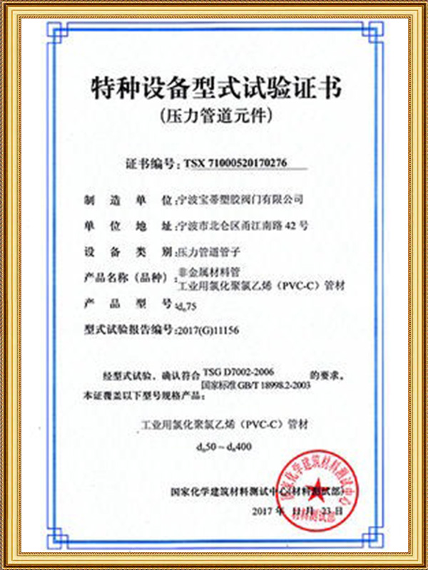
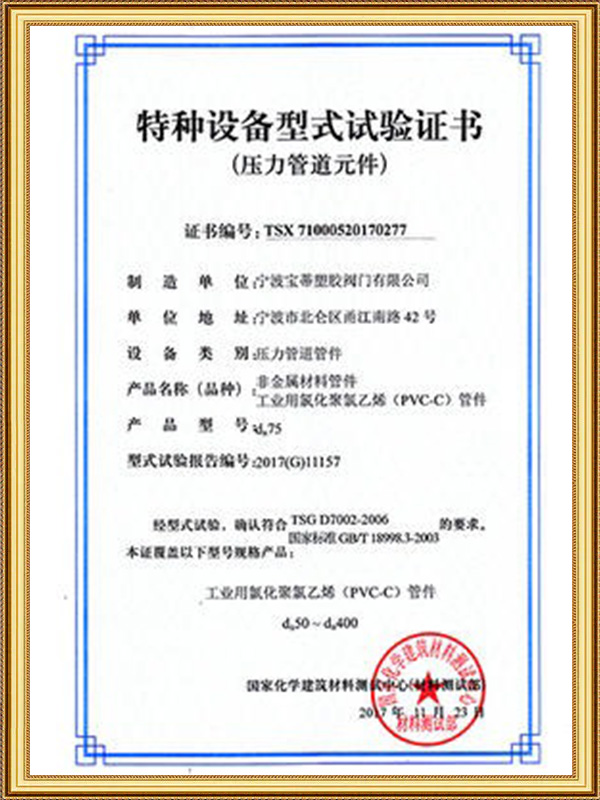
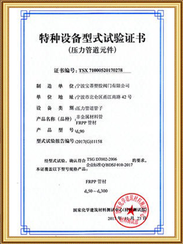
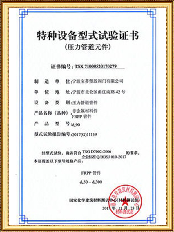
Ningbo Baodi Plastic Valve Co., Ltd. maintains ISO 9001, ISO 14001 and ISO 45001 certification supporting dimensional consistency for header and manifold projects, and exports its piping fitting range, including tees across the full material and size spectrum described above, to distributor and project-contractor clients in more than 60 countries.