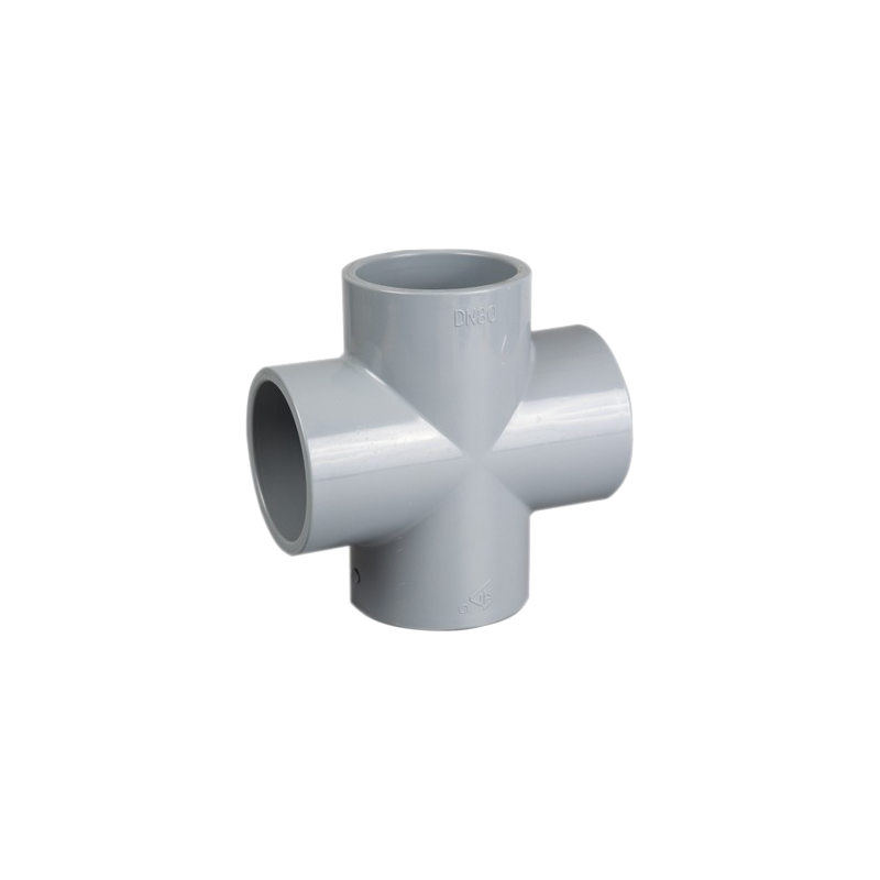
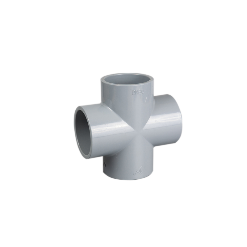
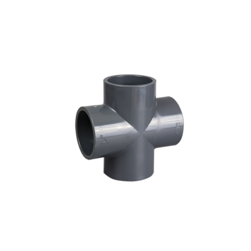
A four-way Plastic Pipe Fitting Cross is specified far less frequently than a tee, reflecting deliberate design practice rather than incidental preference. Three criteria determine whether a given junction should use a cross or two offset tees instead, and working through these criteria explicitly at the design stage produces a more defensible specification than defaulting to whichever configuration happens to be more familiar to the person making the layout decision.
Ningbo Baodi Plastic Valve Co., Ltd. has supplied plastic piping fittings alongside its industrial valve product lines since expanding into industrial plastic pipes and fittings in 2006, with crosses specified selectively for grid-distribution systems and symmetric branch layouts where project design specifically calls for them, reflecting the more selective application pattern discussed throughout this section.
Criterion One: Does the Junction Require Genuinely Symmetric Four-Way Distribution?
A cross divides flow in three directions simultaneously at a single point, producing a flow pattern that is harder to predict than a tee, where only two downstream paths require evaluation. This added complexity arises because each of the three downstream paths in a cross junction interacts with the other two simultaneously, rather than the sequential, more isolated two-path evaluation possible at a standard tee, making the overall flow-balance calculation for a cross junction meaningfully more involved even before considering the practical difficulty of achieving genuinely matched resistance across three separate downstream paths rather than two.
Applications with genuinely symmetric requirements — sprinkler and fire-protection grids, where pipes branch in two perpendicular directions with reasonably balanced flow expectations — fit a cross directly, since the underlying system design already assumes and is engineered around roughly symmetric distribution at each grid junction, making the cross's inherent flow-splitting behavior an appropriate match for the application's actual requirements rather than a complicating factor. Where the two branch directions actually serve different, unrelated functions with different flow requirements — for example, one branch continuing a main distribution run while the other serves an unrelated auxiliary connection with entirely different flow and pressure requirements — the case for a single cross weakens relative to two independently sized and independently specified tees, since forcing two functionally unrelated branches through a single shared junction adds complexity without a corresponding benefit.
Criterion Two: Is Installation Space a Genuine Constraint?
Two closely spaced 90° tees generally produce more predictable, individually analyzable flow behavior than the three-way split inside a single cross, which is why piping design practice generally favors that configuration for general branch lines outside of applications specifically requiring symmetric distribution. Where layout space allows two separated tees without difficulty, that configuration should be evaluated first, since the flow-predictability advantage discussed under Criterion One generally outweighs the modest footprint savings a cross would provide in an installation where space is not genuinely constrained.
Where installation space genuinely does not allow two separated tees — a common situation in compact equipment skids, congested mechanical rooms, or retrofit projects working within an existing structure's fixed dimensions — a single cross achieves equivalent four-way connectivity in a meaningfully more compact footprint. This space constraint is a legitimate and sufficient reason to choose a cross specifically, even in an application that does not otherwise require symmetric distribution, provided the flow-balance implications discussed under Criterion One are understood and, where necessary, addressed through balancing valves on the connected branches.
Criterion Three: Does the Governing Design Code Address Cross Use Directly?
Project specifications, particularly in fire-protection and grid-distribution work, frequently define where crosses may or may not be used explicitly, rather than leaving the decision to general engineering judgment based on the space and symmetry considerations discussed under Criteria One and Two. Fire-protection design codes in particular often address cross fitting use directly as part of their broader hydraulic calculation and system design requirements, since the flow-predictability considerations that make crosses a more selective general-purpose choice become critical in a life-safety system where guaranteed minimum flow at every sprinkler head must be demonstrable through calculation.
This code-level requirement should be confirmed before applying Criteria One and Two independently, since a code requirement supersedes the general preference framework above — an engineer who determines, based purely on space and symmetry considerations, that a cross would be the more efficient choice at a particular junction, but who has not checked whether the governing fire-protection or piping design code restricts or prohibits cross use at that type of junction, risks specifying a configuration that will not pass code review or inspection regardless of its technical merit under the general engineering criteria discussed above.
Cross Fitting Types
A straight (equal-size) cross has four ports of matching diameter, applicable in symmetric grid systems where all branches carry comparable flow — the most common configuration in sprinkler grid and similar symmetric distribution applications, where uniformity of branch size across the grid simplifies both the hydraulic calculation and the physical installation, since every cross in the grid uses identical fittings regardless of its position within the overall layout.
A reducing cross has one or more branch ports smaller than the main run, applicable where perpendicular branches serve smaller downstream demand than the primary line — a less common configuration than the straight cross, generally reserved for applications where the symmetric four-way junction requirement of Criterion One and the branch-sizing logic discussed in relation to reducing tees both apply simultaneously at the same location, a relatively specific combination of circumstances that arises less frequently than either consideration alone.
Trade-Offs of Cross Selection
| Factor |
Cross |
Two Offset Tees |
| Flow predictability |
Lower — three-way split at one point |
Higher — two sequential two-way splits |
| Support requirement |
Concentrated load at one location |
Load distributed across two points |
| Joint count |
Fewer |
More |
| Installed footprint |
More compact |
Requires more layout length |
These trade-offs mirror, in some respects, the joint-count and footprint considerations discussed in relation to reducing tees versus separate tee-and-reducer assemblies, though the flow-predictability consideration specific to crosses is a more significant factor in the cross decision than the analogous considerations are for reducing tees, since a reducing tee's branch-and-main-run split is inherently simpler to analyze than a cross's three-way split regardless of the specific dimensions involved.
Common Field Corrections and Retrofit Scenarios
Field crews occasionally encounter a situation where a cross was specified during design but, once installation begins, one of the four branches turns out to be unnecessary — perhaps a planned future connection was cancelled, or a design revision eliminated one of the intended branch lines. In this scenario, the cross is typically still installed as specified, with the unused branch simply capped, rather than substituting a tee at that stage of construction, since substituting a different fitting type mid-project generally requires re-procurement and introduces schedule risk that capping an unused branch on an already-delivered cross does not. This does mean the unused branch becomes a dead-leg consideration in its own right, following the same dead-leg risk principles discussed in relation to pipe end caps, and should be evaluated against those same water-quality, sediment and temperature-stratification risks if the capped branch will remain unused for an extended period.
Conversely, retrofit projects sometimes need to add a new branch connection at a location where only a tee currently exists, effectively requiring conversion from a two-way branch to a four-way one. Because a cross and a tee are not interchangeable simply by adding a branch on site, this generally requires replacing the existing tee with a cross entirely — cutting out the tee, verifying the resulting gap and alignment against the new cross's dimensions, and installing the cross with appropriate support for its four connection points, following the same installation and support principles discussed above for a new-build cross installation.
Ningbo Baodi Plastic Valve Co., Ltd. has supplied crosses for exactly this kind of retrofit conversion scenario, where an existing tee-based grid required expansion to accommodate an additional branch connection not anticipated in the original design, drawing on the company's broader piping fitting manufacturing experience since 2006 to help confirm that the replacement cross's dimensions and pressure rating matched both the existing pipe run and the new branch's requirements before the retrofit work proceeded.
Design Requirements Once a Cross Is Specified
Connecting branches of similar length and resistance on both sides of the cross improves flow-distribution predictability, partially offsetting the flow-prediction disadvantage relative to sequential tees discussed under Criterion One. Where the two branches connected to a cross's perpendicular ports genuinely serve comparable downstream loads with comparable pipe lengths and comparable connected equipment, the practical flow-imbalance risk is considerably reduced compared with a cross connecting two branches of substantially different length or resistance, even though the underlying three-way split geometry remains inherently more complex to analyze than a sequential two-tee configuration in either case.
Because a cross creates four connection points at one location, adequate access space must be planned for installation, inspection and future maintenance — a requirement that is easy to underestimate given the fitting's compact footprint, since the same space-saving characteristic that makes a cross attractive under Criterion Two can also mean less working room is available around the fitting for a technician to access all four connections during a future maintenance event, compared with the more spread-out access typically available around two separated tees serving the equivalent function.
Structural and Support Considerations
The concentrated load path at a cross junction, noted in the trade-off table above, deserves specific attention during support design. Where two offset tees distribute their respective branch loads across two separate support points along the header, a single cross concentrates the combined load of both perpendicular branches at one location, meaning the support at that single point must be designed to carry a correspondingly greater combined load than either individual tee support would need to carry on its own. Underestimating this concentrated load requirement, by applying a support specification sized for a standard tee rather than accounting for the additional branch load a cross introduces, is a specification error that can lead to inadequate support and, over time, stress-related joint issues at the cross connection.
Material Options
PVC crosses serve ambient-temperature water distribution and fire-protection grid systems where applicable, representing the material most commonly associated with general building sprinkler and water distribution grid applications. CPVC extends this into hot water and higher-temperature applications, and is in fact a particularly common material choice for fire-protection sprinkler systems specifically, given CPVC's widespread use and code acceptance in that application. PP crosses, generally fusion-joined, suit acid, alkaline and wastewater grid distribution systems in industrial rather than building-service contexts. PVDF crosses serve aggressive chemical distribution systems requiring broad chemical resistance, a less common but not unheard-of application for four-way symmetric distribution in specialty chemical processing contexts. The three selection criteria above apply consistently regardless of material, since they concern the fitting's geometric and hydraulic behavior rather than its chemical or thermal properties.
Ningbo Baodi Plastic Valve Co., Ltd. produces crosses across this material range on an order basis, reflecting the more selective and typically lower-volume nature of cross fitting demand compared with the company's tee, elbow and coupling product lines, which see substantially higher standard demand across general industrial and water treatment project work.
Procurement Specification
Project buyers should confirm whether a straight or reducing cross is required, all four port sizes, connection method, and pressure/temperature rating consistent with the rest of the distribution system. For fire-protection and grid-distribution projects, buyers should confirm whether crosses are required or restricted by the applicable design code per Criterion Three before finalizing the order, ideally as an early step in project specification rather than a late-stage check performed only after a cross-based layout has already been developed in detail.
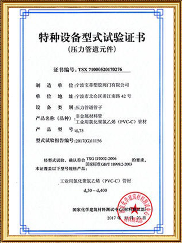
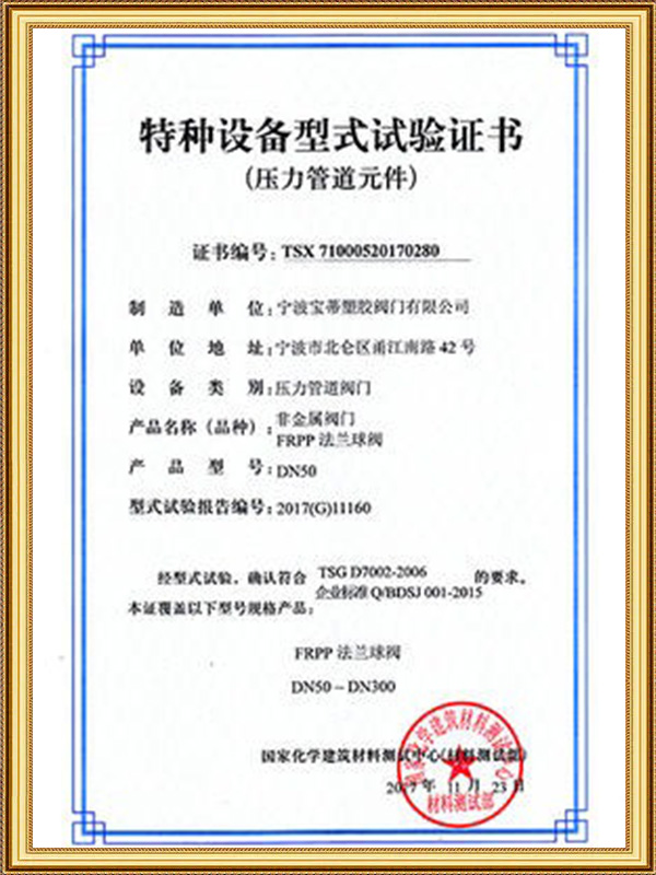
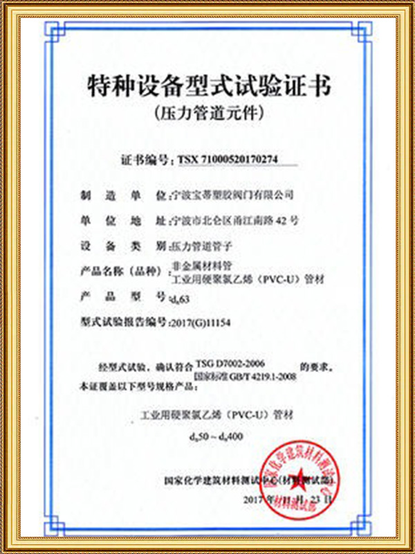
Distributors supplying fire-protection and water-grid contractors typically stock crosses in the size ranges most common to grid layouts, while general process-piping distributors stock them in more limited sizes given their more selective application. Ningbo Baodi Plastic Valve Co., Ltd. exports to more than 60 countries with ISO 9001, ISO 14001 and ISO 45001 certification supporting consistent fitting quality for both standard branch fittings and less-common four-way distribution components, and draws on manufacturing experience dating to the company's 1979 founding to support distributors and project contractors specifying crosses correctly against the criteria discussed throughout this section.