How Does an Automatic Butterfly Valve Control Large Industrial Pipelines?
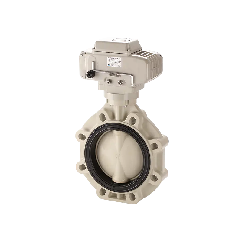
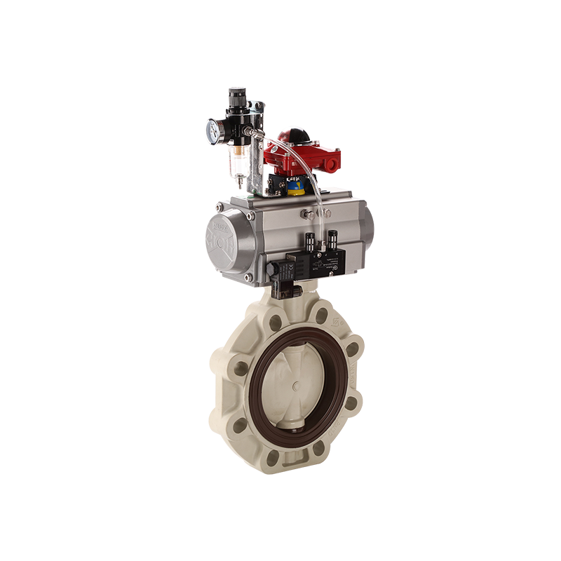
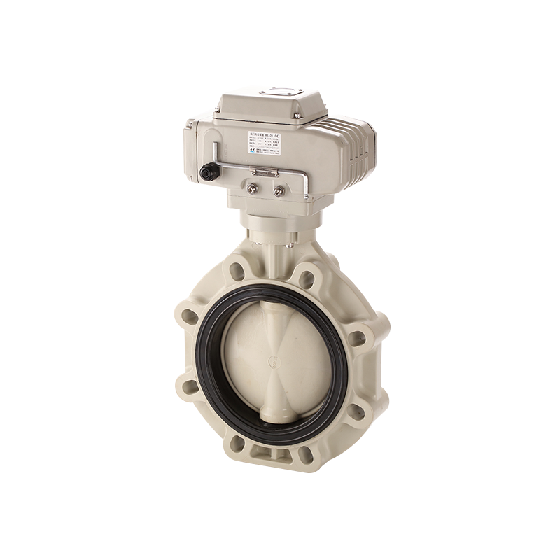
Large industrial piping systems often require remote operation, reliable shut-off and clear valve-position feedback. Manual operation becomes difficult when valves are installed on elevated pipelines, inside restricted areas or close to corrosive chemicals. An Automatic Butterfly Valve addresses these conditions by combining a compact butterfly-valve body with an electric, pneumatic or hydraulic actuator.
The actuator rotates the internal disc through a controlled angle. When the disc is nearly parallel to the direction of flow, the valve is open. When the disc rotates approximately 90 degrees and becomes perpendicular to the pipeline, the passage is closed.
An Automatic Butterfly Valve has a relatively short face-to-face dimension and lower weight than many other large-diameter valve structures. This makes it suitable for water treatment, chemical processing, cooling circulation, wastewater handling, irrigation and automated equipment.
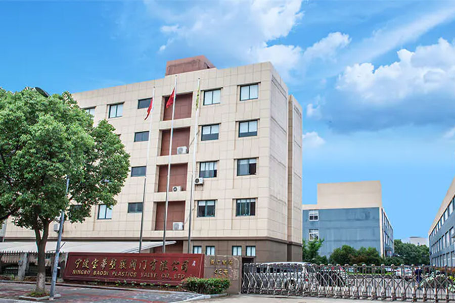
Ningbo Baodi Plastic Valve Co., Ltd. traces its origins back to 1979 and is one of the earliest enterprises in China to design and manufacture industrial plastic valves. Its experience in thermoplastic valves, pipes and fittings supports the selection of corrosion-resistant Automatic Butterfly Valve products for demanding industrial systems.
What Is an Automatic Butterfly Valve?
An Automatic Butterfly Valve is a quarter-turn valve consisting of a valve body, rotating disc, shaft, valve seat, actuator, mounting bracket and control accessories.
The actuator converts electricity, compressed air or hydraulic pressure into rotational movement. This movement is transmitted through the shaft to the disc.
Automatic isolation: The valve can open or close a pipeline without direct manual operation.
Flow control: A modulating actuator can position the disc at different angles to regulate flow.
Equipment interlocking: The valve position can be linked with pumps, tanks, filters and process-control equipment.
Emergency operation: The actuator can move the valve to a predefined position after an abnormal process signal or utility failure.
Remote monitoring: Limit switches and position transmitters can report the actual valve position to a control system.
Ningbo Baodi Plastic Valve Co., Ltd. developed from Zhenhai Chemical Valve Factory and Beilun Plastic Valve Factory. Its long experience with industrial chemical valves provides a practical understanding of how disc material, valve-seat compatibility and actuator torque influence automatic operation.
How Does an Automatic Butterfly Valve Work?
Opening Sequence
The opening process begins when the control system sends a command to the actuator. An electric actuator starts its motor, while a pneumatic actuator receives compressed air through a solenoid valve.
The actuator output shaft rotates the valve shaft. The disc moves away from the closed position and gradually increases the available flow area.
When the required angle is reached, a limit switch or positioner stops the actuator. The control system may then receive a signal confirming that the valve is open or positioned correctly.
Closing Sequence
During closing, the actuator rotates in the opposite direction. The disc edge moves toward the valve seat and compresses the sealing surface.
The actuator must provide enough torque to overcome seat friction, process pressure and fluid forces acting on the disc.
Insufficient torque may leave the valve partly open. Excessive torque may over-compress the seat and shorten its service life.
Ningbo Baodi Plastic Valve Co., Ltd. has manufactured industrial plastic valves for more than four decades. Accurate control of body, shaft, disc and seat dimensions helps maintain stable closing torque and repeatable positioning.
Disc Angle and Flow Rate
The disc angle and actual flow rate do not change in direct proportion. At small openings, a slight angle change may create a significant increase in flow.
Near the fully open position, additional disc movement may produce only a limited increase in flow capacity.
This non-linear characteristic must be considered when an Automatic Butterfly Valve is used for regulation rather than simple isolation.
Travel Adjustment
Actuator travel must match the real disc position. Insufficient travel can cause internal leakage or restrict full-flow capacity.
Excessive closing travel can damage the valve seat, shaft or actuator coupling. Mechanical stops and electrical limits should therefore be adjusted carefully.
Main Components of an Automatic Butterfly Valve
Valve Body
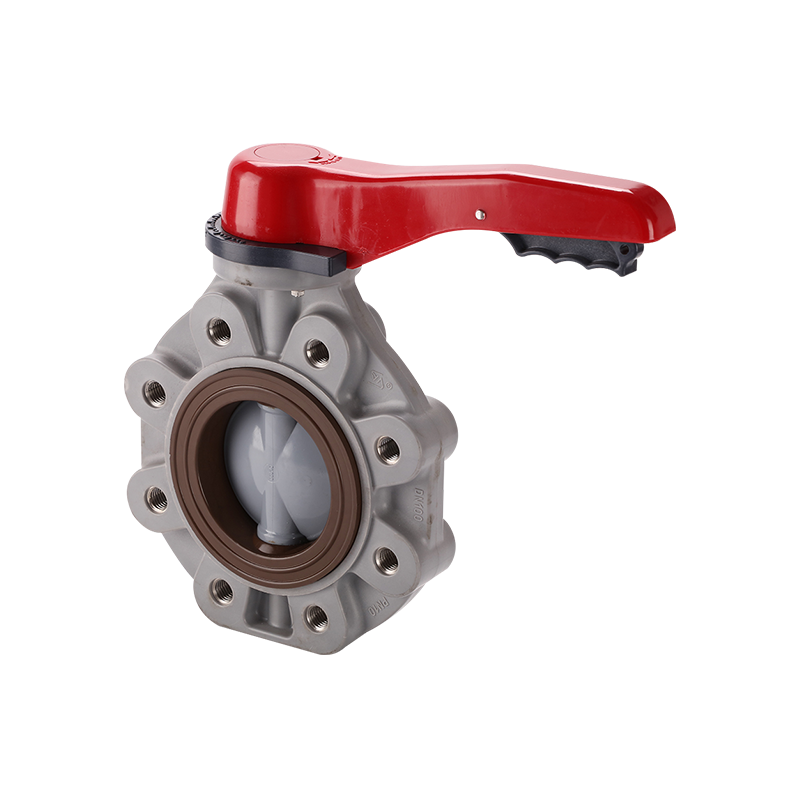
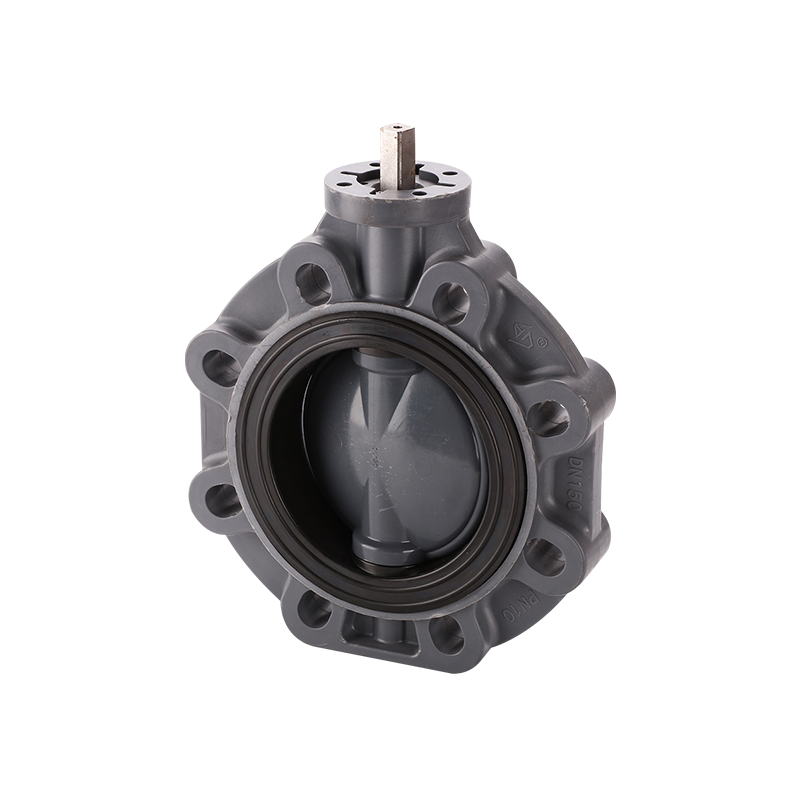
The valve body supports the disc, shaft, seat and actuator connection. Common structures include wafer, lug and flanged bodies.
The body must withstand internal pressure, flange-clamping force and pipe movement. In thermoplastic valves, excessive bolt force or unsupported piping may deform the body and interfere with disc movement.
Ningbo Baodi Plastic Valve Co., Ltd. expanded its product range in 2006 to include industrial plastic pipes and fittings. This allows an Automatic Butterfly Valve and its connected piping to be selected according to compatible materials and dimensions.
Disc
The disc is the main flow-control component. Its thickness, contour and material affect pressure loss, operating torque and flow coefficient.
The disc remains exposed to the process medium in both open and closed positions. Its chemical compatibility must therefore be checked separately from the valve body.
Shaft
The shaft transfers actuator torque to the disc. Some valves use a continuous shaft, while others use upper and lower shaft sections.
The shaft must provide sufficient strength and corrosion resistance. Poor alignment can increase friction and produce inaccurate valve-position feedback.
Valve Seat
The valve seat forms the main sealing surface around the disc edge. Seat material affects chemical resistance, operating temperature, closing torque and leakage performance.
Chemical swelling, hard particles, temperature changes and repeated cycling can gradually change seat dimensions and sealing force.
Actuator and Mounting Assembly
The actuator provides rotational torque. A mounting bracket and coupling connect the actuator output shaft to the valve shaft.
Incorrect alignment can cause shaft loading, actuator wear or incomplete movement. The mounting structure should remain rigid during the full operating cycle.
Wafer, Lug and Flanged Automatic Butterfly Valve
Wafer Automatic Butterfly Valve
A wafer Automatic Butterfly Valve is installed between two pipe flanges. Long bolts or threaded rods pass through the flanges and clamp the body in position.
This design is compact, lightweight and suitable where installation space is limited. It is widely used in water, circulation and general industrial systems.
Lug Automatic Butterfly Valve
A lug valve has threaded lugs around the body. Each pipe flange is connected independently.
Some lug designs allow one side of the pipeline to be removed while the valve remains connected to the other side. Dead-end pressure capability must still be confirmed.
Flanged Automatic Butterfly Valve
A flanged valve has integrated flange connections. It normally provides greater installation rigidity and is commonly selected for large-diameter industrial pipelines.
The structure requires more installation space and has greater weight than wafer and lug designs.
Body Style Comparison
| Parameter |
Wafer Type |
Lug Type |
Flanged Type |
| Body structure |
Compact body between flanges |
Body with threaded lugs |
Body with integrated flanges |
| Installation weight |
Low |
Moderate |
High |
| Required space |
Small |
Moderate |
Larger |
| Connection rigidity |
Moderate |
Moderate to high |
High |
| Typical use |
General automated isolation |
Equipment and branch pipelines |
Large industrial pipelines |
The broad thermoplastic piping range of Ningbo Baodi Plastic Valve Co., Ltd. helps users coordinate valve-body style, flange dimensions and pipe materials throughout a complete system.
Concentric and Eccentric Automatic Butterfly Valve Designs
Concentric Design
In a concentric Automatic Butterfly Valve, the shaft centerline, disc center and valve-body center are generally aligned.
The disc remains in contact with the resilient seat during much of its rotation. This structure is simple and widely used in water treatment, irrigation and moderate-pressure chemical systems.
Continuous seat contact produces noticeable friction, which must be included in actuator sizing.
Double-Eccentric Design
A double-eccentric valve positions the shaft away from the disc sealing center and the pipeline centerline.
The disc separates from the seat more quickly during opening, reducing running friction and seat wear.
This design is suitable for larger valves, higher operating frequency and greater pressure differences.
Triple-Eccentric Design
A triple-eccentric valve adds an angled sealing geometry. The sealing surfaces contact mainly during final closure.
This structure is often used in high-temperature or demanding pressure applications and may use a metal sealing system.
Design Comparison
| Design |
Seat Contact |
Typical Seat |
Torque Characteristic |
Typical Application |
| Concentric |
Contact during most of rotation |
Elastomer or polymer |
Moderate friction |
Water and general chemical systems |
| Double eccentric |
Disc separates quickly |
Soft or reinforced seat |
Reduced running torque |
Higher-cycle industrial pipelines |
| Triple eccentric |
Contact mainly near closure |
Metal sealing structure |
Higher final seating torque |
High-temperature and demanding service |
Electric, Pneumatic and Hydraulic Automatic Butterfly Valve
Electric Automatic Butterfly Valve
An electric actuator uses a motor and gearbox to rotate the disc. It is suitable where compressed air is unavailable.
Selection should consider voltage, output torque, operating time, duty cycle, control signal and environmental protection.
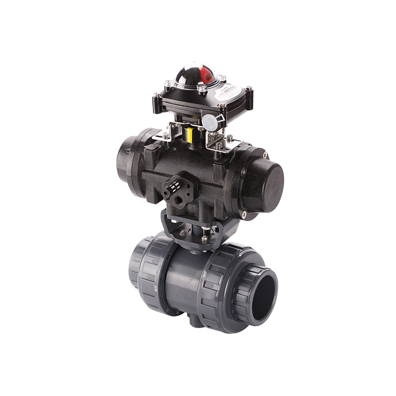
Pneumatic Automatic Butterfly Valve
A pneumatic actuator uses compressed air to drive a rack-and-pinion or scotch-yoke mechanism.
Pneumatic operation is fast and suitable for frequent cycling. It may use a double-acting design or a spring-return fail-safe structure.
The air supply should remain clean, dry and stable.
Hydraulic Automatic Butterfly Valve
A hydraulic actuator uses pressurized fluid to produce high torque. It is mainly used for very large valves or special high-load applications.
Actuator Comparison
| Parameter |
Electric Actuator |
Pneumatic Actuator |
Hydraulic Actuator |
| Power source |
Electricity |
Compressed air |
Hydraulic pressure |
| Operating speed |
Moderate |
Fast |
Adjustable |
| Output torque |
Depends on motor and gearing |
Moderate to high |
High |
| Fail-safe option |
May require backup power |
Practical with spring return |
Requires a dedicated circuit |
| Typical use |
Remote operation without plant air |
Frequent cycling and interlocks |
Large or high-torque valves |
Ningbo Baodi Plastic Valve Co., Ltd. exports industrial thermoplastic products to more than 60 countries. Different site conditions show that actuator selection should be based on available utilities, operating frequency and required fail-safe action.
On-Off and Modulating Control
On-Off Control
An on-off Automatic Butterfly Valve moves between fully open and fully closed positions. It is used for equipment isolation, circulation switching, tank control and emergency shut-off.
Limit switches normally confirm that the commanded position has been reached.
Modulating Control
A modulating Automatic Butterfly Valve can stop at intermediate angles to regulate flow, pressure, liquid level or temperature.
A positioner compares the requested signal with the actual disc angle and adjusts the actuator accordingly.
The valve should be sized so normal operation does not remain continuously at a very small opening. Small openings create high local velocity, noise, vibration and seat erosion.
Common Control Signals
| Signal Type |
Main Function |
| Digital on-off signal |
Full opening or closing |
| Analog signal |
Proportional disc positioning |
| Pneumatic control signal |
Direct actuator positioning |
| Digital communication |
Position control and diagnostics |
Flow Characteristics, Cavitation and Water Hammer
Pressure Loss
The disc remains in the flow passage even when the valve is fully open. Pressure loss is influenced by disc thickness, shaft diameter, valve size, opening angle and fluid velocity.
Cv or Kv data should be reviewed when the Automatic Butterfly Valve is used for flow regulation.
Cavitation
High pressure differences can cause local pressure to fall below the fluid vapor pressure. Vapor bubbles may form and collapse downstream.
Repeated cavitation can damage the disc edge, valve seat and nearby piping.
Water Hammer
Rapid closure can create water hammer in large-diameter, high-flow or long piping systems.
An actuator speed controller or programmed closing time can reduce sudden changes in fluid velocity.
Ningbo Baodi Plastic Valve Co., Ltd. manufactures complete industrial thermoplastic piping products, so valve operation should be considered together with pipe pressure, supports and system layout.
Fail-Safe Operating Positions
Fail Closed
A fail-closed Automatic Butterfly Valve moves to the closed position when air or power is lost.
This arrangement is commonly selected for chemical isolation and emergency shut-off.
Fail Open
A fail-open valve moves to the open position after utility failure.
It may be used in cooling-water and protective-circulation systems where continued flow is necessary.
Fail in Place
A fail-in-place valve remains near its last position after power or air is lost.
This may be suitable where temporarily maintaining the existing process condition is preferable.
| Design |
Position After Utility Failure |
Typical Application |
| Fail closed |
Closed |
Chemical isolation and emergency shut-off |
| Fail open |
Open |
Cooling and protective circulation |
| Fail in place |
Last position |
Temporary process-position retention |
Torque Requirements and Actuator Sizing
Seating and Unseating Torque
The actuator must overcome friction between the disc and seat when the valve begins to open. It must also provide enough force to compress the seat during final closure.
Dynamic Torque
Flow acting on a partially open disc creates dynamic torque. This load may become significant at intermediate disc angles.
Velocity, pressure difference and disc geometry all influence the dynamic load.
Main Torque Factors
Valve diameter: Larger discs normally require greater torque.
Maximum differential pressure: Higher pressure across the disc increases operating load.
Seat material: Hardness, friction and chemical swelling affect opening and closing torque.
Operating temperature: Temperature can change seat dimensions and material properties.
Deposits and particles: Accumulation may interfere with disc rotation.
Pipe alignment: External stress may distort the body and increase torque.
The actuator should include a reasonable safety margin. An undersized actuator may stop before reaching the required position, while an oversized actuator may damage the shaft, seat or coupling.
Valve Body, Disc and Seat Materials
PVC
PVC is commonly used for ambient-temperature water and selected chemical systems. Its allowable pressure decreases as temperature rises.
CPVC
CPVC provides improved temperature capability compared with standard PVC.
Ningbo Baodi Plastic Valve Co., Ltd. was one of the first domestic enterprises to apply CPVC to industrial-grade piping valves.
PP
PP is suitable for many acids, alkaline fluids and wastewater applications. Its pressure capability depends on temperature and material grade.
PVDF
PVDF is selected for many aggressive chemicals and high-purity systems. Compatibility must still be checked for the exact concentration and temperature.
Seat Material Comparison
| Seat Material |
Main Characteristic |
Typical Application |
Main Limitation |
| EPDM |
Good water and alkaline resistance |
Water treatment and selected chemicals |
Generally unsuitable for petroleum oils |
| NBR |
Good oil resistance |
Air, oil and selected industrial fluids |
Limited resistance to oxidizing chemicals |
| FKM |
Resistance to many oils and chemicals |
Chemical and oil-related systems |
Not suitable for every alkaline medium |
| PTFE |
Broad chemical resistance |
Corrosive chemical service |
Requires suitable structural support |
| Reinforced PTFE |
Improved strength and stability |
Higher-load sealing conditions |
Reinforcement compatibility must be checked |
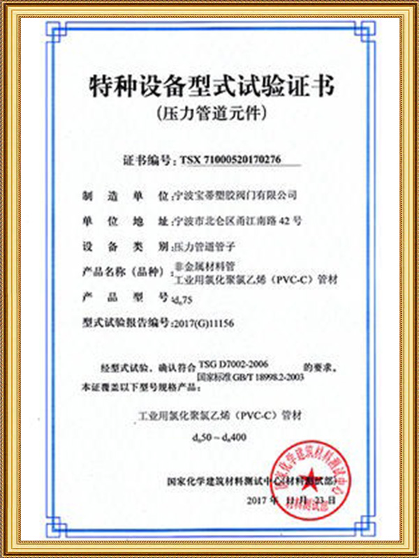
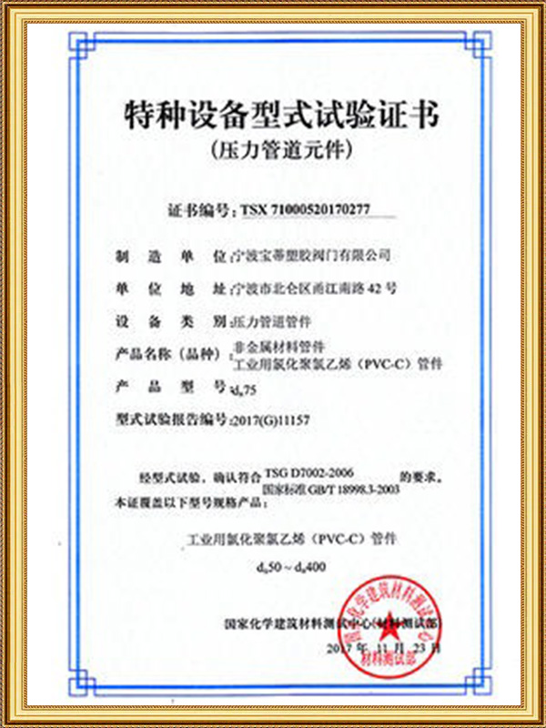
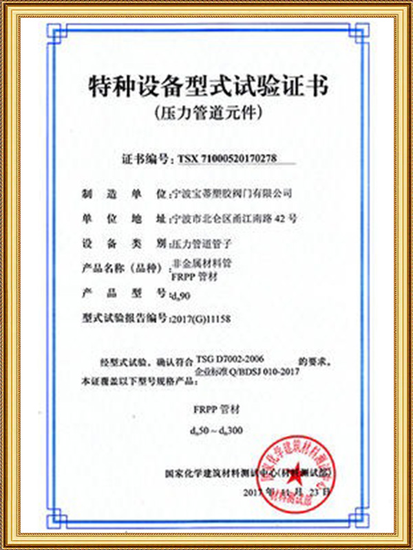
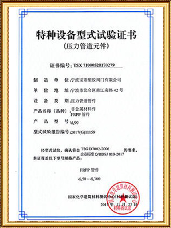
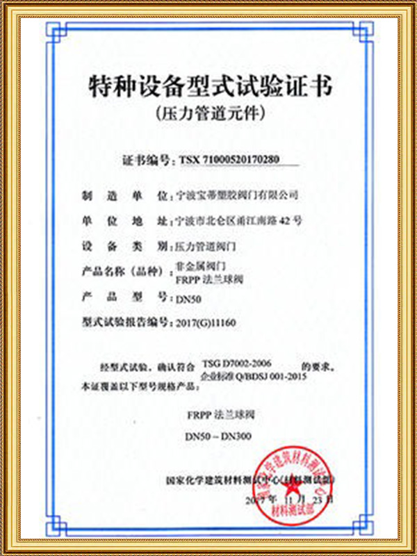
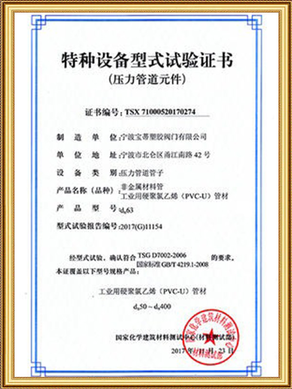
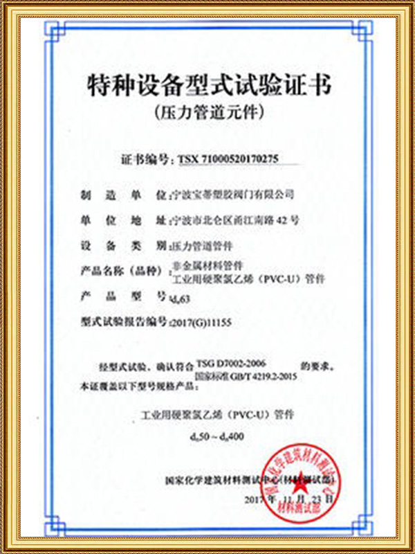
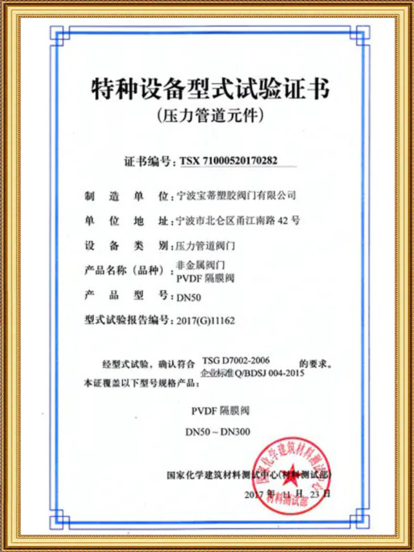
Ningbo Baodi Plastic Valve Co., Ltd. has obtained ISO 9001, ISO 14001 and ISO 45001 certifications, together with the national special equipment pressure piping component manufacturing license. These qualifications reflect the importance of controlled materials and pressure performance.
How to Select the Right Automatic Butterfly Valve
Identify the Process Medium
Confirm the medium name, concentration, temperature, viscosity and particle content.
Check whether the fluid may cause corrosion, swelling, abrasion, crystallization or deposits.
Determine the Control Function
The Automatic Butterfly Valve may be required for isolation, regulation, emergency shutdown, circulation control or equipment interlocking.
Choose the Body Style
A wafer body is suitable where compact size is important. A lug body may be useful for independent flange connections. A flanged valve provides greater rigidity in large pipelines.
Select Materials
The body, disc, shaft, seat and seals should all be checked separately for compatibility with the process medium.
Choose the Actuator
Pneumatic actuation suits frequent and fast operation. Electric actuation is practical where compressed air is unavailable. Hydraulic actuation may be required for very high torque.
Confirm Torque and Fail-Safe Position
The actuator must cover seating, unseating and dynamic torque. The failure position should be selected according to equipment protection and process risk.
Ningbo Baodi Plastic Valve Co., Ltd. ranks among manufacturers with a broad range of industrial thermoplastic valve and piping products, helping users coordinate connection standards and material compatibility throughout the system.
Installation and Commissioning Guidelines
Inspect the Valve
Inspect the body, disc, seat, shaft, actuator, bracket and coupling before installation.
Clean and Align the Pipeline
Remove sand, welding residue, plastic particles and sealing material. The flanges should be parallel and correctly centered.
The valve should not be used to pull misaligned pipes into position.
Keep the Disc Slightly Open
During installation, keep the disc slightly open to prevent the edge from being compressed or scratched by the flanges.
Confirm that the flange inside diameter allows free disc rotation.
Tighten Bolts Evenly
Tighten bolts gradually in a cross pattern. Uneven force may deform a thermoplastic body or valve seat.
Test Direction and Feedback
Confirm that the opening and closing signals match the actual disc movement. Adjust mechanical limits and verify position feedback.
The fail-safe function and manual override should also be tested before operation.
Routine Maintenance and Troubleshooting
Valve Does Not Reach the Required Position
Possible causes: Insufficient actuator torque, incorrect limit settings, disc interference, seat swelling, shaft damage or coupling movement.
Internal Leakage
Possible causes: Seat damage, disc-edge wear, trapped particles, insufficient closing travel or body deformation.
Slow or Unstable Movement
Possible causes: Low air pressure, actuator overload, incorrect positioner settings, excessive dynamic torque or increased shaft friction.
Incorrect Position Feedback
Possible causes: Loose limit switches, coupling clearance, shaft movement or incorrect calibration.
Excessive Noise or Vibration
Possible causes: Long-term small-opening operation, high velocity, excessive pressure difference or cavitation.
Ningbo Baodi Plastic Valve Co., Ltd. has served tens of thousands of enterprises domestically and internationally. Field experience shows that many Automatic Butterfly Valve problems are related to incorrect actuator sizing, unsuitable materials or installation misalignment.
Typical Applications of an Automatic Butterfly Valve
Water and Wastewater Treatment
The valve is used in raw-water, filtration, backwash, circulation and drainage pipelines.
Chemical Processing
Thermoplastic Automatic Butterfly Valve products can handle many corrosive fluids when all wetted materials are compatible.
Cooling and Circulation Water
The valve may regulate flow according to pressure, temperature or equipment operating signals.
Irrigation Systems
Automatic operation allows large branches and filtration equipment to be controlled without frequent manual intervention.
Tank and Pump Systems
The valve can be interlocked with liquid-level instruments and pumps to control filling, discharge and circulation.
Frequently Asked Questions About Automatic Butterfly Valve
Does an Automatic Butterfly Valve Require Electricity?
An electric valve requires electricity. A pneumatic valve uses compressed air, although the solenoid valve and feedback devices may also require electrical power.
Can an Automatic Butterfly Valve Regulate Flow?
Yes. A modulating actuator and positioner can adjust the disc angle. The valve should not remain continuously at an excessively small opening.
What Happens When Power or Air Fails?
The valve may close, open or remain in its last position depending on the actuator and fail-safe design.
Why Does the Disc Remain in the Flow Path?
The disc is the main control component and remains inside the pipeline. This keeps the valve compact but creates some pressure loss.
Can It Handle Corrosive Chemicals?
It can handle corrosive chemicals when the body, disc, seat, shaft and seals are compatible with the medium, concentration, temperature and pressure.
Why Does the Valve Not Close Completely?
Possible causes include insufficient torque, incorrect travel, damaged seats, trapped particles, body deformation or disc interference.
How Fast Should the Valve Close?
The correct closing time depends on valve diameter, flow velocity and pipeline length. Large high-flow systems normally require controlled closing to reduce water hammer.
Can the Valve Be Operated Manually?
Some actuators include a handwheel or manual mechanism. The automatic power source should be isolated before manual operation.
What Information Is Needed Before Selection?
Required information includes the medium, concentration, temperature, pressure, maximum differential pressure, flow rate, nominal diameter, body style, disc material, seat material, actuator type, control signal, operating time, valve-position feedback and fail-safe requirement.