Technical Guide
Plastic Valve Fittings: Complete Selection, Installation & Troubleshooting Manual for Industrial Fluid Systems
A comprehensive engineering reference covering plastic ball valves and fittings, plastic check valves with barbed tube fittings, PVC fitting taxonomy, connector standards, and field-proven solutions for how to stop a plastic valve from leaking.
Plastic Valve Fittings serve as critical infrastructure components across municipal water distribution networks, industrial chemical processing facilities, agricultural irrigation systems, and residential plumbing installations. The transition from metallic piping systems to thermoplastic solutions has accelerated over the past three decades, driven by superior corrosion resistance, reduced installation weight, and significant cost advantages in both material procurement and long-term maintenance. Understanding the complete technical landscape of plastic valves and fittings empowers engineers, procurement specialists, and installation contractors to specify products that deliver reliable performance across diverse operational environments.
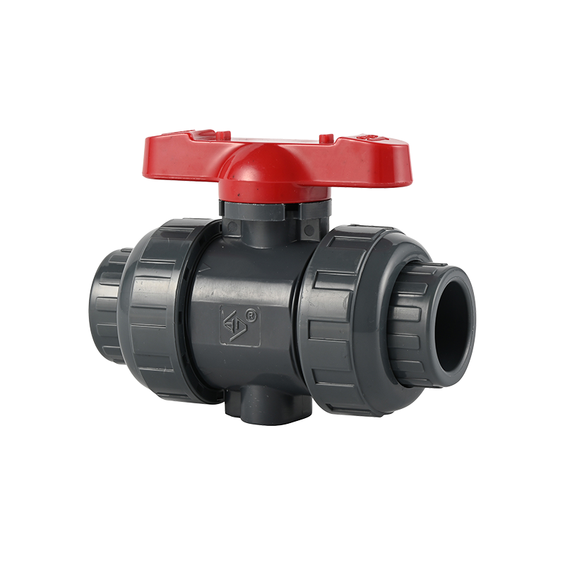
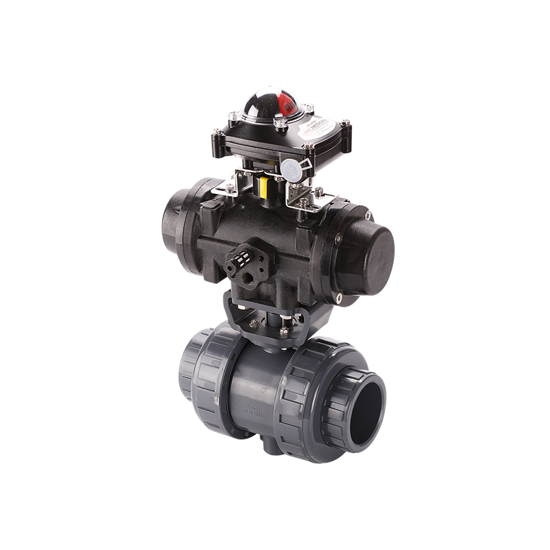
The thermoplastic valve family encompasses several distinct architectures, each engineered for specific flow control applications. Ball valves utilize a spherical closure element rotated ninety degrees to achieve full open or closed positions. The ball contains a precision-machined bore that aligns with the pipeline when open, offering minimal flow restriction. Full port ball valves maintain identical bore diameter to the connecting pipe, eliminating pressure drop across the valve body. Standard port configurations reduce the bore diameter, creating measurable resistance while reducing manufacturing costs and component weight.
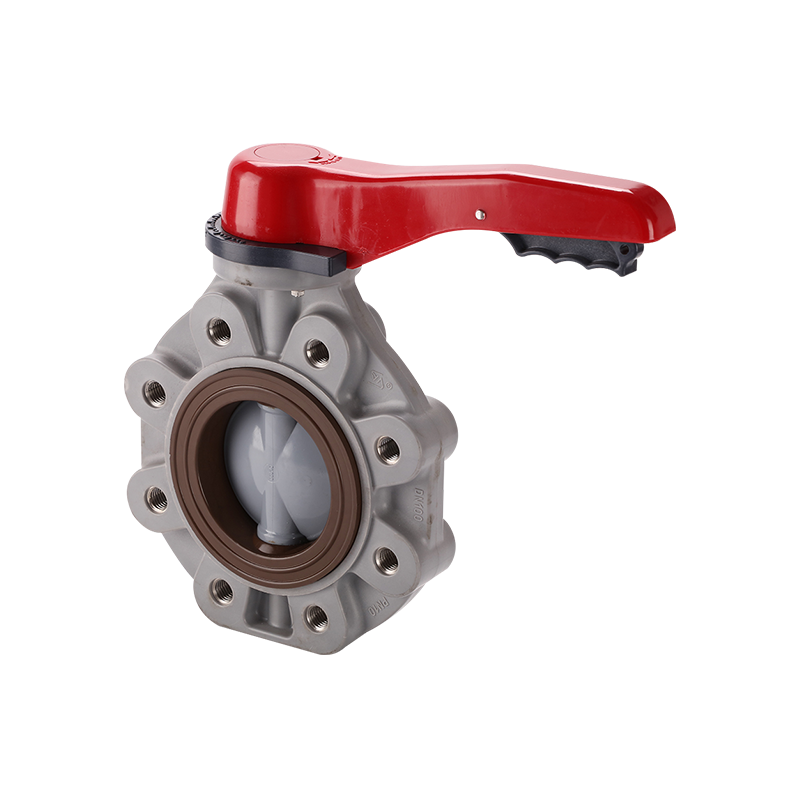
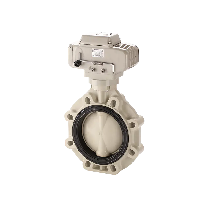
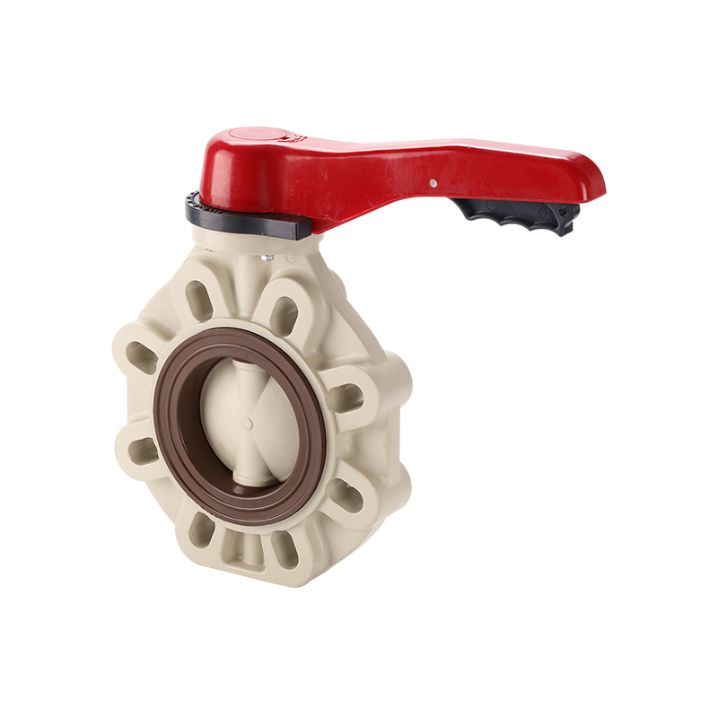
Butterfly valves employ a circular disc mounted on a central shaft that rotates within the flow stream. This design excels in large-diameter applications where space constraints and weight considerations favor compact actuator packages over globe or gate alternatives. The disc position modulates flow proportionally between fully open and fully closed states, making butterfly valves suitable for throttling service where precise flow regulation matters.
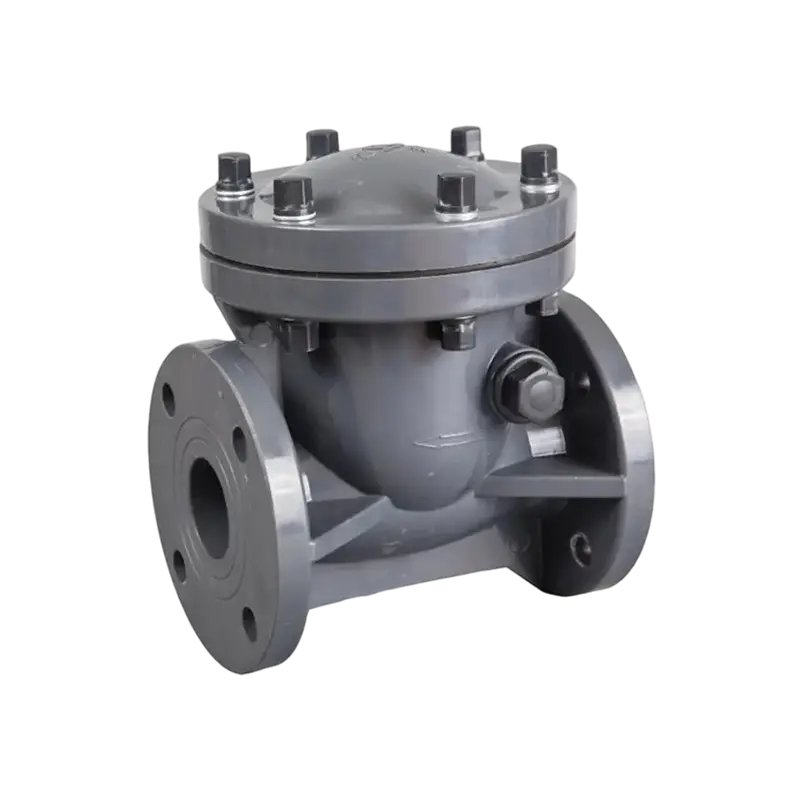
Check valves represent automatic flow control devices that permit forward movement while preventing reverse flow. Swing check designs utilize a hinged disc that opens under forward pressure and closes when flow reverses or stops. Lift check configurations guide the closure element along a vertical axis, responding rapidly to pressure differentials. For low-pressure applications involving flexible tubing, plastic check valves with barbed tube fittings integrate hose connection geometry directly into the valve body.
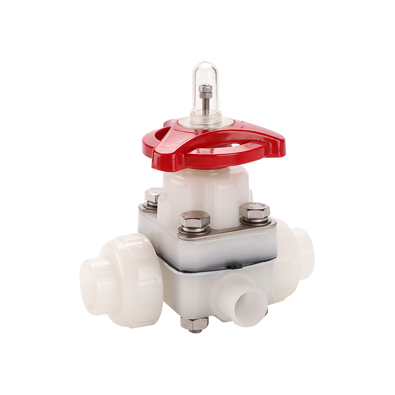
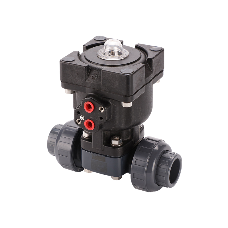
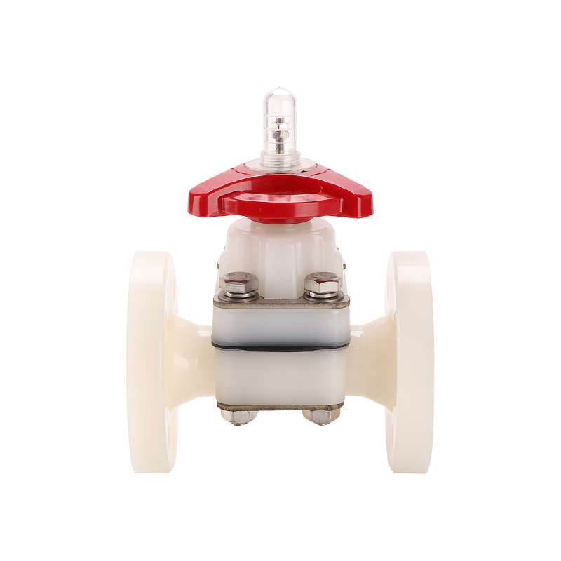
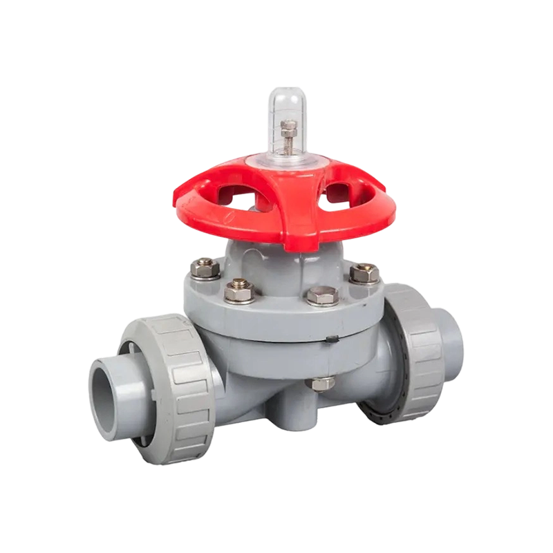
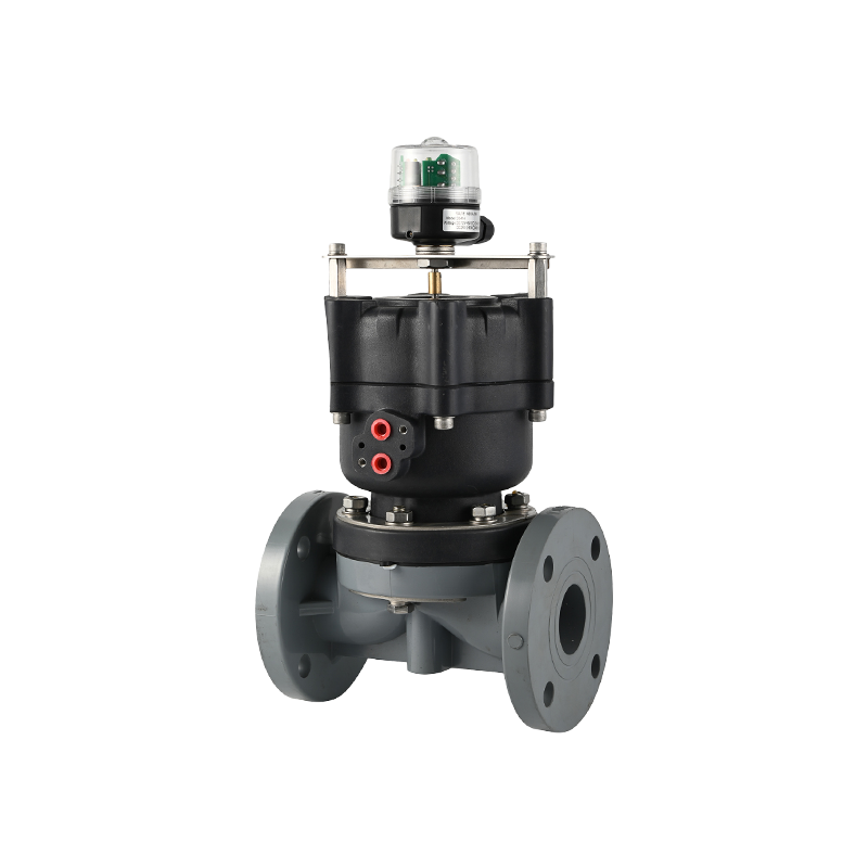
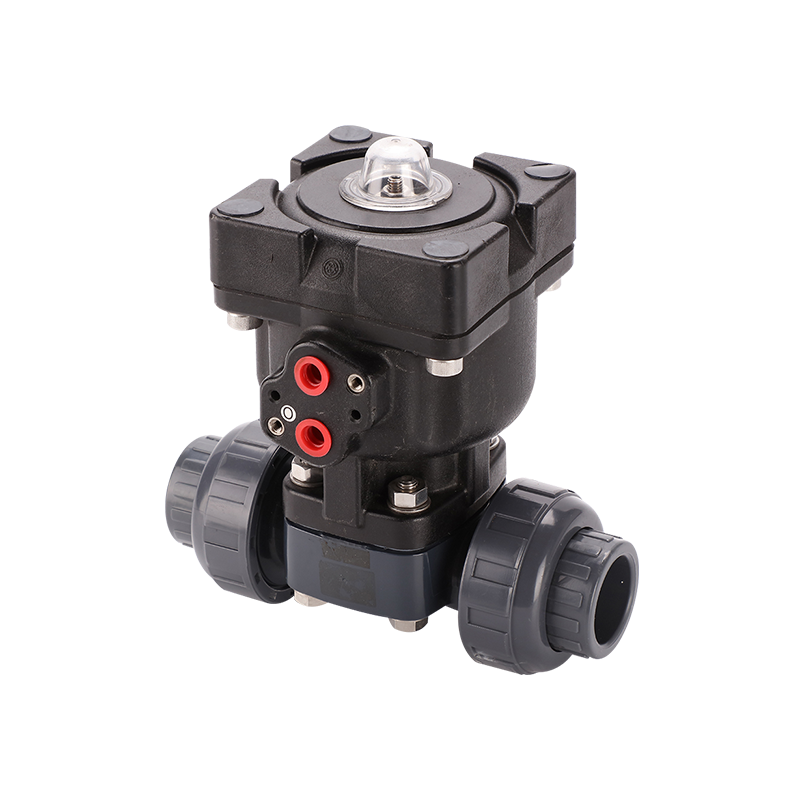
Diaphragm valves isolate the operating mechanism from the process fluid using a flexible elastomeric membrane. The valve stem compresses the diaphragm against a machined weir or saddle to achieve closure. This architecture eliminates packing glands and exposed stems, delivering exceptional chemical resistance and eliminating potential contamination points. Gate valves employ a wedge-shaped closure element that moves perpendicular to the flow direction. The full-bore design minimizes pressure loss when fully open, making gate valves suitable for isolation service in straight-run piping where flow restriction must remain negligible.
Polyvinyl chloride fittings form the geometric backbone of thermoplastic piping systems, enabling directional changes, branch connections, diameter transitions, and terminal closures. Elbow fittings redirect flow through forty-five degree or ninety degree angles. Long radius elbows maintain gradual curvature that minimizes turbulence and pressure loss compared to short radius equivalents. Street elbows feature male threads on one end and female socket on the other, eliminating the need for additional coupling components in tight installations.
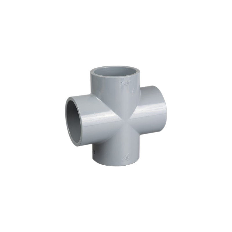
Tee fittings create branch connections perpendicular to the main pipeline. Straight tees maintain identical diameters across all three ports, while reducing tees accommodate diameter changes between the run and branch connections. Cross fittings intersect four ports at ninety degree angles, serving as central distribution nodes in complex manifold assemblies. Coupling fittings join two pipe segments of identical diameter in straight-line continuation. Repair couplings incorporate internal seals and compression sleeves that enable leak repair without system shutdown.
Adapter fittings bridge different connection methodologies, converting socket ends to threaded interfaces or transitioning between plastic and metallic systems. Bushing fittings reduce diameter within a threaded assembly, featuring external male threads on the large end and internal female threads on the small end. Cap fittings terminate open pipe ends using internal socket connections, while plug fittings seal threaded openings from the exterior. Union fittings incorporate separable coupling nuts that enable rapid disassembly for maintenance or component replacement without cutting the pipeline.
Plastic Ball Valves and Fittings: Structural Parameters
Plastic ball valves and fittings combinations require careful specification to ensure compatible pressure ratings, temperature limits, and chemical resistance profiles. Threaded ball valve assemblies typically incorporate female NPT or BSP threads on the inlet and outlet ports. The tapered thread profile creates mechanical interference that seals under torque loading. Socket-fusion ball valves accept plain pipe ends for solvent cement welding, creating monolithic connections that eliminate threaded joint failure modes. True union ball valves incorporate removable carrier sections that allow valve replacement without disturbing adjacent piping.
The operating torque of plastic ball valves varies significantly based on seal material, pressure class, and bore diameter. EPDM seals offer excellent water resistance and moderate chemical compatibility at economical price points. Viton fluorocarbon seals withstand aggressive hydrocarbons, concentrated acids, and elevated temperatures up to four hundred degrees Fahrenheit. PTFE seats provide universal chemical resistance with extremely low friction coefficients, though they require higher seating loads to achieve bubble-tight closure. Handle configurations range from simple lever operators for manual service to padlock-compatible locking levers that prevent unauthorized operation.
Plastic check valves with barbed tube fittings occupy specialized niches within the broader valve ecosystem. The barbed connection geometry eliminates thread engagement entirely, relying instead on radial compression between the valve barbs and the elastic tubing wall. Installation requires heating the tubing end in warm water to temporarily soften the material, then pressing it firmly over the barbed profile until fully seated. Upon cooling, the tubing elastic recovery generates uniform radial pressure across all barb ridges.
This connection method suits applications requiring frequent disassembly or where vibration would loosen threaded joints. Medical devices, food processing equipment, and analytical instrumentation frequently specify barbed check valves for their cleanability and rapid assembly characteristics. The barbed profile features multiple conical ridges that grip the interior wall of silicone, PVC, or rubber tubing without clamps or adhesives. These units typically exhibit cracking pressures between zero point five and two pounds per square inch, making them ideal for gravity-fed systems, aquarium circulation loops, and laboratory equipment where backflow prevention protects sensitive instrumentation.
What are the different types of water valve connectors?
The interface between valves and piping systems determines installation speed, serviceability, and long-term sealing integrity. Slip socket connectors utilize solvent cement welding to chemically fuse the valve body to the pipe end. The process begins with mechanical cleaning using abrasive cloth to remove oxidation and surface contaminants. PVC primer softens the mating surfaces, preparing the molecular structure for chemical bonding. Medium-bodied solvent cement applied to both surfaces initiates polymer chain interdiffusion that creates a homogeneous joint stronger than the base material.
Threaded connectors engage tapered pipe threads with thread sealant or compatible tape to fill surface imperfections and lubricate the assembly. Over-tightening plastic threads generates hoop stress that initiates circumferential cracking; proper torque follows manufacturer specifications precisely. Compression connectors employ a split ring or ferrule that deforms radially against the pipe exterior as a coupling nut advances. The resulting mechanical grip creates a pressure-tight seal without chemical adhesives or thread engagement. Push-fit connectors contain stainless steel gripping teeth and dual EPDM O-rings within a rigid plastic body. Flanged connectors bolt flat mating faces together with an intervening gasket.
Pressure & Temperature Rating Comparison
| Material / Schedule |
1/2" Rating (psi) |
12" Rating (psi) |
Max Temp (°F) |
Temp Factor @ 110°F |
| PVC Schedule 40 |
600 |
130 |
140 |
0.51 |
| PVC Schedule 80 |
850 |
230 |
140 |
0.51 |
| CPVC Schedule 80 |
850 |
230 |
210 |
0.65 |
| PP (Polypropylene) |
150 |
90 |
180 |
0.70 |
| PVDF |
300 |
150 |
280 |
0.80 |
How to fit isolation valve to plastic pipe requires methodical preparation and adherence to material-specific protocols. Begin by depressurizing the system and draining all residual fluid from the installation zone. Mark the pipe at the desired valve location, ensuring adequate clearance for handle operation and future maintenance access. Cut the pipe squarely using a fine-tooth saw or rotary pipe cutter designed for thermoplastic materials. Ragged or angled cuts prevent proper seating in socket connections and create stress concentration points.
Chamfer the pipe end at fifteen degrees using a deburring tool or sharp knife, removing all burrs from both interior and exterior edges. The chamfer guides the pipe into the valve socket without displacing cement or damaging O-ring seals. For slip socket isolation valves, apply primer to the pipe exterior and valve socket interior using the applicator brush attached to the primer can. Allow ten to fifteen seconds for surface softening before applying medium-bodied solvent cement in a uniform layer. Immediately insert the pipe fully into the socket, rotating one-quarter turn to distribute the cement evenly. Hold the joint stationary for thirty seconds to prevent pipe ejection from hydraulic pressure generated during insertion. Avoid disturbing the assembly for twenty-four hours while the cement cures to full strength.
For threaded isolation valves, wrap compatible thread sealant tape clockwise around the male pipe threads, starting one thread back from the pipe end to prevent tape fragments from entering the flow stream. Hand-tighten the valve onto the pipe, then advance one to two additional turns using strap wrenches. Excessive torque cracks female threads or distorts the valve body. Installation orientation significantly affects performance; ball valves may be installed in any orientation, though vertical stem-up positioning minimizes sediment accumulation in the body cavity.
How to cut plastic valve guide to fit addresses situations where standard valve configurations require modification for custom installations. Valve guide bushings center the stem within the body bore, maintaining alignment under operating loads. When replacing worn guides or adapting valves to non-standard actuator configurations, precise length adjustment becomes necessary. Secure the guide bushing in a padded vise, protecting the exterior surface from jaw marks. Mark the cut line using a fine scribe or permanent marker, verifying squareness with a machinist square.
Cut using a fine-tooth hacksaw blade or abrasive cutoff wheel rotating at moderate speed. High cutting speeds melt thermoplastic materials, producing ragged edges and dimensional inaccuracy. After cutting, face the end square using a sharp blade or lathe tool, removing any irregularities that would prevent uniform seating against the stem shoulder. Deburr the interior bore using a twisted wire brush or round file, ensuring the stem moves freely without binding. Chamfer the cut edge at ten to fifteen degrees to facilitate assembly and reduce stress concentration. Measure the final length with calipers, verifying tolerance within plus or minus zero point five millimeters of specification. Apply compatible thread sealant or retaining compound before installing the modified guide into the valve body. Torque to manufacturer specifications using a calibrated torque wrench.
Field modification of plastic valve guide components extends service life in specialized applications. Valve stems experience wear at packing interfaces and bearing points after extended cycling. Guide bushings manufactured from glass-filled PTFE or bronze-filled nylon provide low-friction bearing surfaces that reduce operating torque and extend packing life. When replacing worn guides in existing valve bodies, measure the original bushing outside diameter and body bore inside diameter to determine press-fit or slip-fit requirements. Press-fit installations require heating the valve body bore to approximately one hundred twenty degrees Fahrenheit and chilling the replacement bushing to expand and contract the respective diameters.
How to Stop a Plastic Valve from Leaking?
How to stop a plastic valve from leaking demands systematic diagnosis of the leak source before implementing corrective action. External leakage from the valve body typically indicates cracked housing material from freeze damage, impact, or overtightened connections. Inspect the exterior surface under magnification for hairline cracks radiating from thread roots or socket transitions. Replace cracked valves immediately; thermoplastic repairs using adhesives or patches rarely achieve pressure-rated integrity.
Stem packing leakage manifests as weeping along the valve stem during operation or pressurized standby. Tighten the packing nut one-eighth turn clockwise using an adjustable wrench. If leakage persists after moderate tightening, the packing material has hardened or extruded beyond recovery. Disassemble the valve by removing the handle nut and extracting the handle from the stem square. Loosen the packing nut and remove the old packing rings or V-ring set. Clean the stuffing box and stem surfaces of all residue. Install new packing rings individually, staggering the split joints ninety degrees apart. For PTFE V-ring packing, install the narrow end toward the pressure source. Tighten the packing nut finger-tight plus one-quarter turn. Operate the valve through several full cycles to seat the packing, then retighten as needed.
Seat leakage through a closed ball valve indicates damaged or contaminated sealing surfaces. Disassemble the valve body, inspect the ball and seat rings for scratches or embedded debris. Clean with lint-free cloth and compatible solvent. Replace damaged seats; minor scratches on the ball may be polished using fine abrasive compound. Troubleshooting leakage in plastic check valves with barbed tube fittings involves distinct procedures from threaded or socket systems. Barbed connections rely on elastic interference between the tubing interior diameter and the barb exterior diameter. Leakage indicates insufficient compression from tubing relaxation, barb damage, or improper tubing material selection.
Flow Coefficient (Cv) Comparison by Valve Type
| Valve Type |
Port Configuration |
Cv (% of Pipe Capacity) |
Primary Application |
| Ball Valve (Full Port) |
Full Bore |
95-100% |
Isolation, On/Off Service |
| Ball Valve (Standard Port) |
Reduced Bore |
60-70% |
General Purpose Isolation |
| Butterfly Valve |
Disc Type |
40-60% |
Throttling, Large Diameter |
| Gate Valve |
Full Bore |
90-95% |
Straight Run Isolation |
| Globe Valve |
Reduced / Guided |
30-50% |
Flow Regulation, Throttling |
| Check Valve (Swing) |
Full Bore |
50-70% |
Backflow Prevention |
| Diaphragm Valve |
Weir Type |
40-60% |
Corrosive / Sanitary Service |
Material selection extends beyond PVC into specialized thermoplastics addressing specific operational challenges. CPVC chlorinated polyvinyl chloride extends maximum service temperature to two hundred ten degrees Fahrenheit while maintaining excellent chemical resistance. Polypropylene valves withstand aggressive acids and alkalis that attack PVC, operating from subzero temperatures to one hundred eighty degrees Fahrenheit. PVDF polyvinylidene fluoride delivers exceptional purity and chemical resistance for semiconductor and pharmaceutical applications, though at significantly higher material cost. ABS acrylonitrile butadiene styrene provides impact resistance and cold-temperature ductility for drainage and vent systems where pressure ratings remain modest.
Chemical resistance databases guide material selection for aggressive service environments. PVC demonstrates excellent resistance to inorganic acids including sulfuric, hydrochloric, and phosphoric acids at concentrations up to their maximum aqueous solubility. Strong oxidizing acids including concentrated nitric acid and chromic acid attack PVC molecular chains, producing embrittlement and discoloration. Aromatic hydrocarbons including benzene, toluene, and xylene swell PVC through plasticizer extraction, causing dimensional instability and mechanical weakening. Chlorinated solvents including methylene chloride and trichloroethylene aggressively dissolve PVC, rendering the material unsuitable for these service conditions.
Manufacturing Quality Control & Standards
Manufacturing quality control ensures plastic valve reliability across global distribution networks. Injection molding parameters including melt temperature, injection pressure, cooling rate, and cycle time directly influence molecular orientation, crystallinity, and residual stress within finished components. Dimensional verification using coordinate measuring machines confirms thread profiles, socket depths, and flange bolt circles meet applicable ASTM, ISO, or DIN standards. Hydrostatic pressure testing subjects sample valves to one and one-half times rated working pressure for defined durations, verifying structural integrity without leakage or deformation. Burst testing determines the ultimate pressure capacity, establishing safety factors for regulatory compliance documentation.
Dimensional standards establish interchangeability between valves and fittings from different manufacturing sources. ASTM D2466 defines socket-type PVC Schedule forty fittings with inch-pound dimensions for North American markets. ASTM D2467 extends the specification to Schedule eighty wall thicknesses for elevated pressure service. ISO four five two establishes metric dimensions for PVC pressure fittings serving European and global markets. DIN eight zero six three provides German national standards that often serve as reference specifications for Middle Eastern and African procurement.
System design considerations influence valve placement and specification. Install isolation valves upstream and downstream of critical components to enable service without system-wide shutdown. Position check valves downstream of pumps to prevent backspin and water hammer during power interruption. Maintain minimum straight pipe lengths upstream and downstream of flow control valves to ensure accurate flow measurement and stable control characteristics. Provide adequate support structures that prevent valve body loading from pipe weight or thermal expansion forces.
The phenomenon of water hammer poses particular risks to plastic valve and fitting systems. Rapid valve closure generates pressure waves that propagate through the fluid column at acoustic velocity, potentially exceeding the pressure rating of downstream components. Plastic pipes exhibit lower elastic modulus than metallic systems, resulting in reduced wave propagation speeds but larger diameter changes under pressure transients. Surge pressures in PVC systems can reach five to ten times normal operating pressure during abrupt pump stoppage or fast-closing valve actuation. Mitigation strategies include slow-closing valve operators, surge tanks, pressure relief valves, and air chambers that absorb transient energy.
Proper storage and handling practices preserve plastic valve integrity prior to installation. Exposure to direct sunlight initiates UV degradation of PVC surfaces, producing discoloration and surface embrittlement. Store valves in original packaging within climate-controlled warehouses, maintaining temperatures between forty and ninety degrees Fahrenheit. Avoid stacking heavy pallets directly on valve cartons; distributed loads deform socket openings and distort flange faces. Thread protectors remain in place until final connection to prevent thread damage.
The economic analysis of plastic valve systems encompasses initial procurement, installation labor, maintenance requirements, and service life projections. Thermoplastic valves typically cost thirty to sixty percent less than metallic equivalents in equivalent pressure classes. Installation labor reductions result from lighter component weights, solvent welding speed advantages over threaded metallic assembly, and elimination of welding permits and inspections. Maintenance intervals extend significantly in corrosive environments where metallic valves require periodic replacement or protective coating renewal. Life cycle cost analyses consistently favor plastic valve and fitting systems for water, wastewater, chemical, and irrigation applications where operating conditions fall within thermoplastic capability envelopes.
Application Diversity & Smart Integration
Application diversity drives continuous innovation in plastic valve design. Municipal water treatment facilities specify fusion-bonded ball valves with NSF sixty-one certification for potable water contact. Chemical processing plants utilize lined ball valves where aggressive media would attack standard thermoplastic housings. Agricultural drip irrigation networks deploy pressure-compensating valves with barbed outlets that maintain uniform flow across elevation changes. Swimming pool circulation systems combine multi-port ball valves with union connections that simplify winterization procedures. Marine applications favor glass-reinforced nylon valves that resist UV degradation and saltwater corrosion without metallic components.
The integration of smart monitoring capabilities into plastic valve assemblies represents an emerging capability. Pressure transducers threaded into accessory ports provide real-time system pressure data to building automation systems. Flow meters mounted downstream of balancing valves enable precise hydronic commissioning in HVAC installations. Position switches on ball valve handles confirm valve status remotely, supporting safety interlock systems that prevent pump operation against closed discharge valves. These enhancements leverage the inherent compatibility of thermoplastic materials with electronic sensors while maintaining the cost and corrosion advantages that drove initial plastic valve adoption.
Resin compound formulation determines the fundamental performance envelope of plastic valves and fittings. Unplasticized PVC compounds designated PVC-U provide maximum rigidity and pressure capacity for water distribution and industrial pressure piping. Impact-modified formulations incorporate chlorinated polyethylene or acrylic additives that improve toughness at low temperatures, reducing brittle fracture risk during freeze events or rough handling during installation. Pigment selection affects both aesthetic appearance and UV stability; titanium dioxide loadings above two percent provide effective UV screening for outdoor applications, while carbon black masterbatches deliver superior weathering resistance in exposed installations.
Installation Torque Guidelines for Threaded Plastic Connections
| Nominal Size (inch) |
Hand Tight Turns |
Wrench Turns (max) |
Approximate Torque (in-lb) |
| 1/2 |
2-3 |
1 |
50-75 |
| 3/4 |
2-3 |
1 |
75-100 |
| 1 |
2-3 |
1-1.5 |
100-150 |
| 1-1/2 |
2-3 |
1-1.5 |
150-200 |
| 2 |
2-3 |
1.5 |
200-250 |
| 3 |
2-3 |
1.5-2 |
250-350 |
The assembly sequence for plastic valve systems demands attention to environmental conditions that affect solvent cement curing. Ambient temperatures below forty degrees Fahrenheit slow the evaporation rate of solvent carriers, extending cure times from twenty-four hours to seventy-two hours or longer. High humidity accelerates surface moisture condensation on prepared joints, creating a weak boundary layer that compromises bond strength. Wind exposure in outdoor installations rapidly evaporates solvent from cement surfaces before adequate penetration occurs. Experienced installers construct temporary enclosures or schedule work during favorable weather windows to ensure optimal bonding conditions.
Solvent cement viscosity must match application temperature; thin-bodied cements suit small diameters and warm conditions, while heavy-bodied formulations fill gaps in large-diameter joints and cold weather applications. The transition between plastic valve assemblies and metallic piping systems requires engineered adapter components. Flanged adapters bolt to metallic flanges using standard gasket materials, with plastic flange faces requiring full-face gaskets that distribute bolt loads evenly across relatively flexible thermoplastic surfaces. Threaded adapters engage metallic female threads with compatible sealants; the dissimilar thermal expansion coefficients between plastic and metal demand careful torque management to prevent loosening during temperature cycling.
Endurance Testing & Field Best Practices
Quality assurance testing protocols validate plastic valve performance claims. Dimensional inspection verifies critical features including socket depth, thread pitch diameter, flange thickness, and overall length against drawing tolerances. Visual inspection identifies surface defects including sink marks, weld lines, voids, and discoloration that indicate processing irregularities. Hydrostatic proof testing subjects each production batch to elevated pressure holds that verify structural integrity. Seat leakage testing pressurizes the closed valve to rated working pressure, measuring bubble emission rates through the closure interface. Endurance cycling tests operate valves through thousands of open-close cycles to validate seal longevity and torque stability.
Thermoplastic materials exhibit thermal expansion coefficients approximately five times greater than steel; expansion loops or offsets accommodate dimensional changes without stressing valve connections. Compression adapters grip metallic pipe exterior surfaces with brass or stainless steel ferrules that create mechanical seals without thread engagement. Electrofusion couplings incorporate embedded resistance wires that melt HDPE surfaces when energized, creating homogeneous joints between polyethylene valves and pipes that eliminate potential leak paths. The specification of isolation valves in plastic piping networks balances functional requirements with maintenance accessibility.
Need technical specifications or custom fabrication for your fluid control project? Our engineering team provides detailed material compatibility analysis, pressure drop calculations, and installation guidance for plastic valves and fittings across all standard and specialty thermoplastic compounds.