Manual valves are the most common type of valves in industrial fluid control systems and are widely used in petroleum, chemical, electric power, metallurgy, water treatment, papermaking, pharmaceutical, food and other industries. Manual valves use manual operating handles, handwheels, sprockets and other mechanical devices to open and close or adjust the flow of media. It has a simple structure, is easy to use, economical and reliable, and is an indispensable component in industrial pipeline systems. According to the different structural forms, working principles and applicable occasions, manual valves can be mainly divided into the following common types:
Manual gate valve
The manual gate valve realizes the on-off control of the fluid by moving the wedge-shaped or parallel gate up and down. The contact area between the gate and the valve seat is large during opening and closing, which is suitable for full opening or full closing occasions, but not suitable for frequent opening and closing or throttling. The manual gate valve has the advantages of low fluid resistance, good sealing performance, simple structure and long service life. It is widely used in oil pipelines, water treatment, power station systems and other working conditions with high sealing requirements.
Manual ball valve
The manual ball valve uses the ball to rotate 90° around the valve axis to control the flow of the medium. The ball valve opens and closes quickly, has a small operating torque, and has excellent sealing performance. It is particularly suitable for systems that require fast opening and closing and frequent operation. It is suitable for clean liquids, gases and corrosive media. It is widely used in petrochemical, natural gas, pharmaceutical, papermaking and other industries. Its compact structure is particularly suitable for installation in limited spaces.
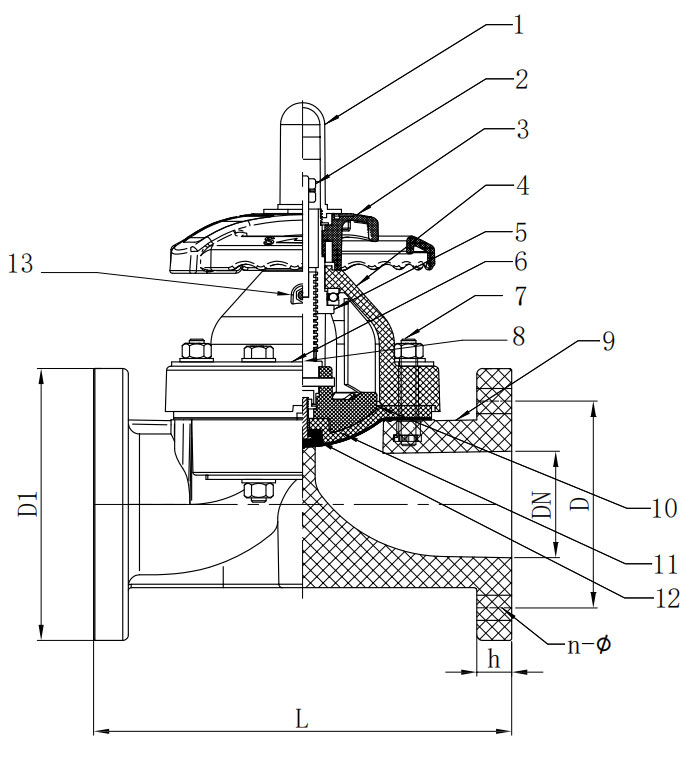
Manual stop valve
The manual stop valve adjusts the flow rate by moving the valve disc in the vertical direction along the center line of the valve seat. Compared with the gate valve, the stop valve has better adjustment performance, but the fluid resistance is relatively large. The stop valve is suitable for occasions where precise control of flow or pressure is required, such as boiler equipment, steam systems, chemical processes, etc. The stop valve has a simple structure and is easy to maintain, and is often used in small and medium-sized pipelines.
Manual butterfly valve
The manual butterfly valve uses a disc-shaped valve plate to rotate around the valve axis to open and close the medium channel. It has a compact structure, light weight and low cost, and is particularly suitable for the control of large-diameter valves. It is commonly used in water treatment, air conditioning systems, fire protection pipelines, food and beverage industries. Although the sealing performance is not as good as that of ball valves and gate valves, it has obvious advantages in space and weight sensitive occasions. Improved products such as bidirectional seals and eccentric butterfly valves can effectively increase its application range.
Manual plug valve
The opening and closing parts of the manual plug valve are conical or cylindrical plugs, which are opened and closed by rotation. Its flow channel is usually straight-through with low fluid resistance. The structure is simple and suitable for frequent opening and closing. It is widely used in oil field exploitation, gas transmission, urban pipe networks and other fields. Since plug valves are prone to wear, modern plug valves often use lubrication or soft sealing structures to improve service life and sealing performance.
Manual diaphragm valve
The manual diaphragm valve uses a flexible diaphragm as an opening and closing part, which is suitable for controlling pipeline systems containing solid particles, corrosive media or viscous fluids. Its biggest advantage is that there is no metal part in contact with the medium, avoiding corrosion and pollution problems. It is suitable for high-clean process flows such as pharmaceuticals, food, and biochemicals, and is widely used in CIP/SIP systems. Due to its special structure, it is convenient to repair and replace the diaphragm.
![]() |
![]() |
DN |
D1(mm) |
D(mm) |
L(mm ) |
h(mm ) |
n |
φ (mm ) |
||||||||||
HG/DIN |
JIS |
ANSI |
HG/DIN |
JIS |
ANSI |
HG/DIN |
JIS |
ANSI |
|
HG/DIN |
JIS |
ANSI |
HG/DIN |
JIS |
ANSI |
|
15 |
95 |
95 |
95 |
65 |
70 |
60 |
125 |
110 |
110 |
14 |
4 |
4 |
4 |
14 |
15 |
16 |
20 |
105 |
100 |
100 |
75 |
75 |
70 |
135 |
120 |
120 |
16 |
4 |
4 |
4 |
14 |
15 |
16 |
25 |
115 |
125 |
125 |
85 |
90 |
79 |
145/160 |
130 |
130 |
16 |
4 |
4 |
4 |
14 |
15 |
16 |
32 |
135 |
135 |
135 |
100 |
100 |
89 |
160/180 |
160 |
160 |
16 |
4 |
4 |
4 |
18 |
19 |
16 |
40 |
145 |
145 |
145 |
110 |
105 |
98 |
180 |
180 |
180 |
16 |
4 |
4 |
4 |
18 |
19 |
16 |
50 |
160 |
160 |
160 |
125 |
120 |
121 |
210/230 |
210 |
210 |
18 |
4 |
4 |
4 |
18 |
19 |
19 |
65 |
180 |
180 |
180 |
145 |
140 |
140 |
250 |
250 |
250 |
22 |
4 |
4 |
4 |
18 |
19 |
19 |
80 |
195 |
195 |
195 |
160 |
150 |
152 |
300 |
280 |
280 |
25 |
8 |
8 |
4* |
18 |
19 |
19 |
100 |
215 |
220 |
220 |
180 |
175 |
190 |
350 |
340 |
340 |
25 |
8 |
8 |
8 |
18 |
19 |
19 |
125 |
255 |
255 |
255 |
210 |
210 |
216 |
405 |
405 |
405 |
30 |
8 |
8 |
8 |
18 |
19 |
22 |
150 |
280 |
280 |
280 |
240 |
240 |
241 |
460 |
460/480 |
460/480 |
30 |
8 |
8 |
8 |
22 |
23 |
22 |
200 |
340 |
340 |
340 |
295 |
290 |
298 |
575 |
575 |
575 |
38 |
8 |
12* |
8 |
22 |
23 |
22 |
250 |
395 |
395 |
395 |
350 |
355 |
362 |
685 |
685 |
685 |
38 |
12 |
12 |
12 |
22 |
25 |
26 |
300 |
480 |
480 |
480 |
400 |
400 |
432 |
790 |
790 |
790 |
40 |
12 |
16* |
12 |
22 |
25 |
26 |
Manual needle valve
The needle valve uses a slender conical valve core to accurately control small flows. Mainly used in high-precision fluid regulation, such as instrumentation systems, sampling systems, hydraulic or pneumatic control circuits. Compact structure, high regulation accuracy, widely used in scientific research, laboratories and high-pressure gas devices.
Manual check valve
Although check valves usually work automatically, some systems use check valves with manual functions. Used to prevent medium backflow and allow manual intervention under special circumstances. Commonly used in high-safety occasions such as high-pressure boilers, pumping stations, chemical storage tanks, etc.
Manual three-way valve
Three-way manual valves can be divided into "T-type" and "L-type" structures, suitable for changing fluid direction or realizing multi-channel switching. It is mostly used in mixing, diversion or bypass systems, and is widely used in HVAC, food processing and pipeline switching. Flexible operation, diverse structure, can be combined with ball valves, plug valves and other forms of design.
Manual ball valves and manual gate valves are two common pipeline cut-off valves, widely used in industrial systems such as petroleum, chemical, metallurgy, electric power, and construction. Although both of them play the role of opening and closing fluids and cutting off passages in terms of function, there are essential differences in their structural design, sealing principle, performance and applicable scenarios.
Structural design differences
The structural core of the manual ball valve is a hollow sphere, which controls the on and off of the medium by rotating the sphere. The sphere is usually a solid metal ball with a hole, which is axially connected to the valve stem. The ball valve is usually a quarter-turn structure, and it only needs to rotate 90° to switch from full open to full closed. The valve body structure is mostly two-piece or three-piece, which is convenient for maintenance and replacement of internal parts. The surface of the sphere is precisely machined and cooperates with the sealing seat to form a sealing pair. The overall structure is compact and light, which is easy to install in places with limited space.
The main structural components of the manual gate valve are wedge-shaped or parallel gates, which are opened and closed by vertically lifting the gate up and down. The gate rises and falls along the spiral motion of the valve stem, usually a multi-turn structure, and the opening and closing process is relatively slow. The gate valve body is generally an integral casting with a deep internal cavity and large structural dimensions. Since the gate needs to be fully raised to the top of the valve cavity to fully open, the manual gate valve has higher requirements for space and operating torque than the ball valve.
Difference in sealing method
The manual ball valve adopts a face sealing structure. The sealing pair is formed by the contact between the surface of the ball and the sealing seat, which is usually made of polytetrafluoroethylene (PTFE), reinforced polymer, metal or composite material. The ball always keeps in contact with the sealing surface during rotation, and effective sealing is achieved through the floating ball or fixed ball design. The ball valve has excellent sealing performance and extremely low leakage rate, which is particularly suitable for working conditions with high requirements for zero leakage. Some high-end ball valves also have two-way sealing and fireproof and anti-static structures to improve system safety.
The manual gate valve adopts a wire sealing structure. The sealing pair is formed by the edges on both sides of the gate and the sealing surface of the valve seat. The sealing surface is mostly made of metal materials such as alloy steel, hard alloy, and Stellite. The sealing depends on the cooperation of the medium pressure and the wedge tightening force of the gate, and the sealing effect is not as good as the ball valve under low pressure conditions. Due to the strong friction between the gate and the valve seat during the opening and closing process, it is easy to wear, and the processing and assembly accuracy requirements are high. Some gate valves use elastic gates or pressure self-sealing structures to enhance sealing, but their overall sealing performance is still slightly inferior to that of ball valves.
Differences in opening and closing performance
The manual ball valve opens and closes quickly, has low torque, and is easy to operate. Its rotation angle is only 90°, which is suitable for systems that are frequently operated or require rapid medium cutoff. There is no friction during the opening and closing process, and the action is stable, which is particularly suitable for occasions that require emergency shutdown.
The manual gate valve opens and closes slowly, and the handwheel needs to be rotated several times to complete the entire operation. Due to the long up and down movement of the gate, coupled with the mechanical loss of the valve stem thread transmission mechanism, the operation process is time-consuming and laborious. It is not suitable for frequent opening and closing, but has reliable long-term sealing capabilities in large-diameter, low-frequency pipeline systems.
Differences in scope of application
The manual ball valve is suitable for pipeline systems that require fast opening and closing, good sealing, and low flow resistance. It is particularly suitable for industries with strict leakage control such as natural gas, refined oil, fine chemicals, pharmaceuticals, and water treatment. It has a compact structure and flexible installation, and is suitable for equipment or branch pipelines with limited space.
Manual gate valves are suitable for trunk pipelines with large diameters, low frequency operations, and small pressure changes. They are widely used in the main valve position of water plants, heating, electricity, metallurgy and other systems, and are especially suitable for use as cut-off devices. Its flow resistance is extremely low, and there is almost no pressure drop in the fully open state, which is more friendly to long-distance transmission systems.
Flow capacity and pressure loss
The channel inside the ball of the manual ball valve is often designed with a full-bore design. The medium has almost no flow resistance when passing through the valve, and no obvious pressure drop is generated. It has little impact on system efficiency and is suitable for process flows requiring efficient transmission.
Manual gate valves also have a small flow resistance in the fully open state, but are prone to turbulence and vibration when partially or incompletely opened. Compared with ball valves, their local structures are more likely to cause medium erosion, which in turn affects the life of the sealing surface.
![]() |
![]() |
In the food and pharmaceutical industries, manual valves not only bear the basic opening, closing, regulation and cutting functions, but are also related to product safety, cleanliness and production compliance. Since these industries have extremely high requirements for hygiene, materials, and anti-pollution capabilities, the selection must strictly follow the relevant industry standards and fully consider factors such as medium characteristics, process flow, cleaning and disinfection methods, and valve structure materials.
Structural design that meets hygienic standards
The food and pharmaceutical industries have extremely high requirements for the cleanliness of equipment surfaces. Manual valves must have characteristics such as no dead angles, no retention, and easy cleaning. When selecting, valve products that meet hygienic certifications such as EHEDG (European Hygienic Engineering Design Group), 3-A (American Dairy Hygiene Association Standards), and FDA (American Food and Drug Administration) should be given priority. The valve cavity should adopt a full-bore design to ensure that the medium flows smoothly without retention; the internal surface should be electrolytically polished, and the roughness should be controlled within Ra ≤ 0.4 μm to avoid bacterial adhesion.
Selection of valve body materials and sealing materials
Material selection directly affects the corrosion resistance, temperature resistance, and biocompatibility of the valve. The food and pharmaceutical industries recommend the use of 316L stainless steel as the main material for the valve body because of its excellent corrosion resistance and weldability, and its ability to withstand the acid, alkali and high-temperature steam environments commonly used in CIP (Clean-in-Place) and SIP (Sterilize-in-Place) systems. Seals should be made of FDA-certified food-grade polytetrafluoroethylene (PTFE), EPDM (ethylene propylene diene monomer rubber) or FKM (fluororubber) and other materials with good chemical resistance and heat resistance to ensure that the medium is not contaminated.
Easy to CIP/SIP cleaning and sterilization
During the production of food and medicine, the piping system needs to be regularly cleaned in place (CIP) and steam sterilized in place (SIP). The valve structure needs to be compatible with this type of cleaning. When selecting, consider whether the valve cavity has an automatic emptying function, whether it can achieve residue-free cleaning, whether the seal has high temperature resistance (≥150°C), and whether the valve supports the sterilization cycle time (generally required to be more than 30 minutes). The structures of three-way valves, diaphragm valves and aseptic sampling valves have been optimized and are more suitable for such processes.
Preferred sanitary valve types such as diaphragm valves and butterfly valves
Diaphragm valves are widely used in places with high cleanliness requirements because their media only contact the inner cavity of the valve body and the diaphragm material. Its structure is simple and there is no retention area in the valve cavity, which is particularly suitable for conveying high-viscosity, solid particles or corrosive media. Butterfly valves have the characteristics of compact structure, light weight, and rapid opening and closing. They are often used in low-pressure or high-flow situations, especially for filling, filtration, and transportation. Sanitary butterfly valves are usually equipped with quick-release clamp connections, which are easy to disassemble, clean and maintain on site, and meet GMP specifications.
Connection method should meet sanitary requirements
The connection method of manual valves is directly related to sanitary sealing performance. Sanitary connection methods such as clamp type, welding type or flange type should be preferred. Clamp type connection can be quickly disassembled and assembled, suitable for equipment that is frequently cleaned; welding type connection has good structural strength and sealing, suitable for permanent assembly occasions; flange type connection is mostly used in large systems, but sanitary flange sealing structure must be selected. Regardless of the method, the sealing surface must maintain processing accuracy and surface finish to avoid microbial growth.
Anti-mixing and batch control
The multi-variety and small-batch production processes in the food and pharmaceutical industries require higher reliability in valve switching and sealing. Structures such as double-seat valves or anti-mixing valves should be selected to prevent cross-contamination between batches. The valve should have a metal limit positioning function to prevent residue or mixing due to misoperation; at the same time, it should support process parameter recording to meet GMP traceability requirements.
Compliance with GMP and validation requirements
According to the requirements of the Good Manufacturing Practice (GMP) for pharmaceutical production, the equipment should have good verifiability and consistency. The selected manual valve should have validation documents, including material certification, sealing material test report, pressure test report, surface roughness certification, installation drawings, etc. At the same time, the manufacturer needs to provide IQ (installation confirmation)/OQ (operation confirmation)/PQ (performance confirmation) document support to meet the quality management system review.
Corrosion resistance and service life assessment
Common media in the food industry, such as dairy products, juice, soy sauce, and alcohol, have certain acidity and alkalinity; in the pharmaceutical industry, such as ethanol, hydrogen peroxide, and acid disinfectants, are highly corrosive. The valve structure must be able to withstand long-term erosion by cleaning agents and chemical reagents while ensuring service life. It is recommended to use a stainless steel valve body that has been sandblasted + electrolytic polished, and the seal must withstand at least 500 CIP/SIP cycles without failure.
Operational convenience and ergonomic design
As a field operating device, manual valves require good ergonomic design. The handle should be made of non-slip material, with clear markings, accurate opening and closing angles, and suitable for operation with gloves; some high-frequency operating stations can be equipped with limit devices or position indicators. If installed in a high or remote place, a sprocket operating mechanism can be considered to improve the convenience of operation.
Manual valves used in low temperature conditions, especially in cryogenic media conditions such as liquid nitrogen (boiling point is −196°C), must be designed and manufactured with a series of special requirements in mind to ensure that the valves can still operate safely, reliably and for a long time at extremely low temperatures. Liquid nitrogen is widely used in aerospace, electronic manufacturing, medical freezing, biological sample preservation and cryogenic industrial processes, which poses severe challenges to the materials, sealing, operating performance and structural stability of valves. For liquid nitrogen and other cryogenic application environments, manual valves should have the following key design requirements:
Selection of materials with strong low temperature adaptability
Metal materials are usually at risk of brittle fracture under low temperature conditions, so metal parts such as valve bodies, valve covers, valve discs, and valve stems need to use low-temperature materials with good toughness and impact resistance. Common materials include austenitic stainless steel (such as 304L, 316L), 9% nickel steel, aluminum alloy, copper alloy, etc. Among them, austenitic stainless steel has good low-temperature ductility and welding performance, can withstand working temperatures below -200°C, and is widely used in liquid nitrogen pipeline systems. The material must undergo a low-temperature impact test (such as a -196℃ impact toughness test) and have a qualified material quality certificate.
Extended bonnet structure design
Low-temperature valves often use an extended bonnet design (Extended Bonnet), the purpose of which is to keep the packing cavity and operating mechanism away from the low-temperature zone to avoid packing freezing failure or deformation of operating parts. The length of the extended bonnet needs to be determined based on the nominal diameter of the valve, the thickness of the system insulation layer and the operating temperature, usually reaching 250mm to 500mm or more. This structure helps to keep the valve stem working in the normal temperature zone, extend the life of the seal, and prevent the operator from accidentally touching the frostbite due to low-temperature frost.
Low-temperature sealing system design
Seals are prone to hardening, brittle cracking or even failure at extremely low temperatures, so sealing materials with excellent low-temperature performance must be selected. Commonly used low-temperature sealing materials include PTFE (polytetrafluoroethylene), PCTFE (polychlorotrifluoroethylene), PEEK (polyetheretherketone), metal spring-loaded sealing systems, etc. Use lip-shaped, V-shaped, elastic compensation or metal-clad sealing structures to improve the adaptive ability of the sealing surface to temperature changes. The valve seat seal should avoid using rubber materials, because they are prone to hardening, cracking or permanent deformation at liquid nitrogen temperatures.
Low leakage and anti-cold brittle design
The evaporated gas of liquid nitrogen is inert nitrogen. Accumulation in a closed system will cause pressure increase or even explosion risk. Therefore, cryogenic valves must have ultra-low leakage levels. It is recommended to use products that meet low-temperature sealing leakage standards such as ISO 15848-1, API 598, and API 607. The bolts, nuts and other connection parts in the sealing area need to be designed to prevent cold brittleness. Low-temperature resistant steel parts should be selected and equipped with cold-drawn thread structures to ensure that there will be no loosening or sealing failure during thermal expansion and contraction.
Thermal stress resistance and dimensional stability design
The valve frequently switches between normal temperature and low temperature or is in a low-temperature operation state for a long time. The material is prone to thermal expansion and contraction, thereby generating thermal stress. The matching relationship of the thermal expansion coefficients of different components should be controlled during design to prevent shell deformation, seal dislocation or loose connection due to thermal stress accumulation. The matching tolerance between the valve stem, stuffing box and valve body must fully consider the low-temperature shrinkage to avoid the risk of jamming or leakage.
Prevent freezing and jamming of operating mechanisms
Manual valve operating parts (such as handwheels, stem threads, and packing glands) must be prevented from freezing or jamming in low-temperature environments. For this purpose, low-temperature grease should be used to maintain lubrication and prevent water vapor from condensing into ice. Self-lubricating bearings, double-layer seals, nitrogen purges, etc. are used in some structural designs to reduce operating friction and keep the mechanism flexible. In addition, to improve safety and operability, mechanisms with limit switches or torque prompts should be selected to prevent excessive operation from damaging the valve structure.
Vacuum insulation and cold preservation measures
Low-temperature medium valve systems are usually connected to vacuum insulated pipelines. The valve housing and extended valve cover parts need to have good cold preservation designs to avoid cold leakage and frost on the outer surface. The housing can be covered with a vacuum layer, an aerogel insulation layer, or a multi-layer reflective insulation material. For systems that require extremely high insulation performance, a low-temperature valve structure with a double-layer shell and a vacuum interlayer can be selected.
Adapt to special installation and maintenance conditions
Valves in liquid nitrogen systems are often installed outdoors, vertically or inverted, which puts additional requirements on the valve installation posture and operating space. The design should ensure that the valve can still maintain good sealing and opening and closing functions in different installation directions. During maintenance, structures that can replace seals or packings without complete disassembly should be considered, such as top-mounted ball valves, split-structure stop valves, etc., to reduce maintenance costs and operational risks.
In industrial fluid delivery systems, manual valves are the most basic and common control elements, and they undertake important functions such as opening and closing, regulation, diversion, cutoff, backflow prevention, and pressure relief of the medium in the pipeline. Reasonable arrangement of manual valves not only helps to improve the reliability and efficiency of pipeline operation, but also directly affects the maintainability, operational safety and investment economy of the system. The location of the manual valve should be determined comprehensively based on a variety of factors such as process flow, fluid characteristics, system control requirements, personnel operation convenience, and maintenance frequency. In different industries and system structures, manual valves should be set at the following key locations:
Equipment inlet and outlet
All pumps, compressors, heat exchangers, filters, reactors and other key equipment must be equipped with manual valves at the inlet and outlet pipelines. Its function is to achieve independent start and stop, maintenance isolation or emergency cutoff of the equipment. When performing equipment maintenance or troubleshooting, the valve can be closed to prevent medium backflow or leakage to ensure safe operation. The appropriate valve type should be selected according to the equipment pressure level, such as using a stop valve to achieve sealing, or a butterfly valve to achieve rapid opening and closing. For bidirectional operating equipment, the double valve interlock design should also be considered.
Pipeline network branch points and confluence points
There are multiple branches, confluences, bypasses or switching pipelines in the pipeline network. Manual valves must be set at the branch points and confluence points to achieve control and selection of flow direction. For example, when multiple devices share the main transmission pipeline, manual valves can be used to achieve parallel or series operation of the equipment. Setting reasonable branch valves can also effectively isolate local areas and close some pipelines during non-operating periods to save energy and reduce consumption or avoid pollution spread.
Inlet and outlet of storage tanks and containers
The inlets and outlets of various containers such as raw material tanks, buffer tanks, intermediate tanks, and liquefied gas storage tanks must be equipped with manual valves. Valves are used to control the loading and unloading, tank dumping, cleaning and maintenance of the medium in the tank. The bottom valve of the liquid storage tank should also consider the drain design to reduce the accumulation of residual liquid at the bottom of the tank. Common valve types include ball valves, gate valves, angle seat valves, etc., which should have the ability to prevent leakage, flexible operation, and adapt to the characteristics of the medium. For flammable and corrosive medium storage tanks, explosion-proof or corrosion-resistant valves should also be selected.
High-point exhaust and low-point drainage positions
Setting a manual exhaust valve at the high point of the pipeline system can effectively release the air in the system to prevent air blockage, air hammer or flow fluctuations. A drain valve is set at the low point to remove condensate, cleaning fluid or residual liquid after the system pressure test. These valves are usually used frequently during system commissioning, shutdown or maintenance. Structures that are easy to operate quickly should be selected, such as straight-through ball valves, needle valves, quick exhaust valves, etc.
Critical control sections of long-distance transmission pipelines
In cross-plant and long-distance transmission systems, manual valves should be set at reasonable intervals or process control sections to achieve segmented control functions. If a section of the pipeline fails, the problem can be isolated by quickly closing the valve to avoid shutdown of the entire line. The setting position usually refers to distance, drop, terrain changes and pressure loss. It is a common engineering practice to set up a set of manual valves every 200 to 300 meters, especially for long pipeline systems such as oil, natural gas, water supply and heating.
Pipeline junction and system conversion point
At the interface position of different media, different pressure levels or different temperature sections, manual valves can play a physical isolation role to prevent mutual influence. Between the cold and hot medium conversion, compression and pressure reduction systems, shut-off type or double valve configuration manual valves should be set to achieve safe switching. Valves should also be installed in functional sections such as process steering, metering interface, before and after filtration, to facilitate system segmented metering, medium replacement or equipment cleaning.
Pipeline inspection and maintenance bypass
In order not to affect the continuous operation of the main process, bypass pipelines are usually set on both sides of the equipment or pipe section, and manual valves are installed to realize the system inspection and switching functions. When a section of the main pipe needs to be replaced or maintained, opening the bypass valve can keep the system running uninterrupted. The bypass valve configuration should pay attention to the series/parallel relationship and flow resistance balance to prevent excessive pressure difference between the main and secondary flow channels or backflow.
Safety protection and emergency isolation area
In the toxic, harmful and flammable medium conveying system, manual valves should be set at the system entrance, exit and key nodes for emergency isolation operations in case of leakage or fire. Usually used in conjunction with electric and pneumatic quick-cut valves, manual valves are used as redundant means to improve the system safety level. Its layout should be easy for personnel to access, with obvious operating instructions and emergency disposal guidelines.
Instrument measurement pressure point
In order to facilitate the installation and maintenance of online instruments such as pressure, temperature, and flow, manual valves should be set before and after the measuring port and used as isolation valves or vent valves at the pressure point. The valve is usually small in diameter and requires tight sealing and sensitive opening and closing. Needle valves or small ball valves are often used, and the materials must match the measured medium to ensure measurement accuracy and long-term stability.
Positions with strong operability for personnel
Manual valves need to be operated manually on a daily basis, and the layout should follow the principles of ergonomics. The valve should be at a moderate height from the ground to facilitate manual rotation or pulling, and avoid being set in high altitudes, narrow spaces, or strong radiation and high temperature areas. If it must be installed at a high place, a zipper mechanism or remote transmission device should be installed. Outdoor pipelines should consider rain and snow protection and anti-freezing measures, and set up clear signs and maintenance platforms.
During the operation of industrial systems, some manual valves are in a non-operating state for a long time due to process backup, system redundancy, safety isolation or seasonal use. If there is a lack of effective maintenance when they are not opened and closed for a long time, the valve may become stuck, seal aging, rust and fail, which will seriously affect the safety and reliability of the entire system. Therefore, for manual valves in a static state, reasonable maintenance measures must be formulated to manage the system from aspects such as structural protection, seal maintenance, action confirmation, and environmental protection to ensure that they can be put into operation normally at critical moments.
Regular opening and closing operation maintenance
When manual valves are not operated for a long time, the valve stem and valve seat, packing gland, threaded transmission structure and other parts are prone to rust, scaling or stuck, resulting in difficulty in opening and closing or even failure. A regular opening and closing system should be established. According to the importance of the valve, the characteristics of the process medium and the environmental conditions, the opening and closing operation should be performed once every 1 to 3 months. During the opening and closing process, the valve should be operated slowly to the fully open and fully closed state to observe whether it is smooth, whether there is abnormal sound, vibration or excessive operating torque. Valves with significantly increased resistance should be repaired immediately.
Keep the valve internal clean
Impurities, scale, crystals or sludge may be deposited inside the valve that has been stationary for a long time, especially in pipelines that transport solid liquids, corrosive or evaporative media. The valve cavity can be kept clean and dry by flushing, venting or passing inert gas during the maintenance period. For valves with vents or drain ports, the lower end of the valve should be opened for periodic drainage. Before resuming the operation of the deactivated system, the valve cavity condition can be checked through an endoscope to confirm that there is no obvious blockage or corrosion.
Stem lubrication and anti-rust treatment
The opening and closing of manual valves depends on mechanical transmission parts such as valve stems, screws, nuts, etc. If they are not lubricated for a long time, it is very easy to cause operation failure due to rust, dry grinding or cold welding of metal contact surfaces. The valve stem surface should be checked regularly for rust and scratches, and the oxide scale should be removed in time, and special grease with strong low-temperature or high-temperature stability should be applied, such as molybdenum disulfide grease, silicone-based lubricating paste or PTFE sealing grease. For exposed structures such as rising stem valves, protective covers, rainproof cloths or isolation shells should be added to avoid rain and snow erosion and dust adhesion.
Check the integrity of the sealing packing
The sealing packing is in a compressed state for a long time. It is easy to age, harden, cold flow, and lose elasticity under non-operating conditions, causing packing seal failure or valve stem leakage. The tightness of the packing gland should be checked regularly, and the bolt torque should be adjusted appropriately to keep the packing tight but not too tight. If the packing color turns yellow, the surface is cracked, or there is leakage, it is necessary to replace it with a new packing in time. For harsh media, corrosion-resistant packings such as expanded PTFE, graphite braiding, and aramid fiber should be selected, and spring-loaded automatic compensation devices should be considered to maintain the sealing preload.
Maintaining static sealing performance
Some manual valves are in a half-open or fully closed state for a long time, and the contact between the valve seat and the valve disc is subjected to a single-direction static pressure, which is prone to stress relaxation of the sealing surface, medium penetration or microscopic displacement, causing permanent deformation of the sealing ring. It is recommended to periodically switch the valve on and off to change the force direction of the valve disc to avoid seal fatigue. For soft-sealed valves, such as rubber, polytetrafluoroethylene, and elastomer valve seats, long-term pressure should be avoided in the closed state. If the system allows, the valve can be switched to the middle opening during shutdown to reduce the sealing pressure.
Environmental protection and cleaning management
Valves are exposed to harsh environments such as outdoor, high humidity, acid rain, dust, and corrosive gases for a long time, and are prone to structural corrosion, loose connections, and label shedding. The surface of the valve body should be periodically derusted, repainted, and painted with anti-rust paint, and the nameplate, operating handwheel, and bracket parts should be cleaned. For high altitude or cold areas, check whether there is water accumulation in the valve cavity before winter to prevent ice and cracking. Auxiliary devices such as rain covers, thermal insulation cotton, and antifreeze heating belts should be installed for key valves in outdoor pipe networks to ensure that they do not fail due to environmental changes.
Maintenance of handwheels, sprockets and operating mechanisms
Some valves are equipped with transmission auxiliary devices such as handwheels, sprockets, and operating levers. If they are not used for a long time, there may be risks of corrosion and fracture, transmission failure or falling off. The connecting bolts should be tightened regularly, and the idle stroke and linkage angle of the transmission mechanism should be checked to keep lubrication and smooth. The chain of the sprocket-type remote-operated valve should be pulled to test flexibility, and the rusted or aged chain segments should be replaced. For manual valves with positioning devices, check whether the positioning pins and limit nuts are stuck or deformed and failed.
Prevent vibration and loose support
Micro-vibration during the operation of pipelines or equipment may be transmitted to the manual valve in a static state through the pipeline, which may cause loosening of the connecting bolts, seal fatigue, and sinking of the bracket for a long time. The valve support structure, flange connection, and bolt tightening conditions should be checked regularly. If necessary, flexible connections or vibration-damping gaskets should be added to prevent stress concentration or vibration fatigue. An independent support base can be set for heavy valves to ensure uniform force.
Function confirmation before system startup
Before a valve that has not been used for a long time is about to be put back into operation, a professional should conduct an opening and closing test, a sealing performance test, and an operating resistance test. If necessary, remove the valve cover to check the scaling and corrosion of the inner cavity, confirm that the sealing ring is intact, the packing is not aged, and the handwheel is smooth and not stuck. Under important working conditions, a pressure leakage test or air tightness test should also be carried out to ensure that the valve function meets the operating requirements and ensure the safety of the startup of the entire system.
![]() |
![]() |
![]() |