How Do Plastic Pipe Reducers Control Diameter Transitions and Flow Conditions?
Industrial piping systems rarely use one pipe diameter from beginning to end. Pumps, valves, tanks, filters and process equipment often have connection sizes that differ from the main pipeline. A properly selected reducer allows these components to be connected while maintaining a controlled flow path and a practical installation layout.
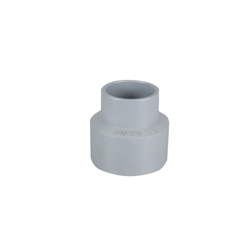
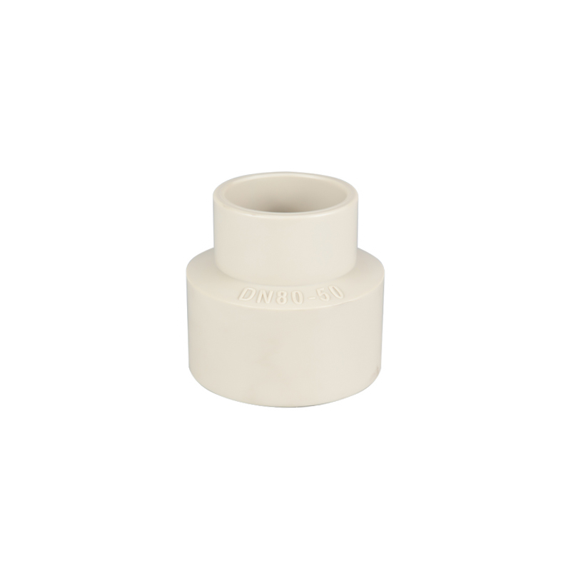
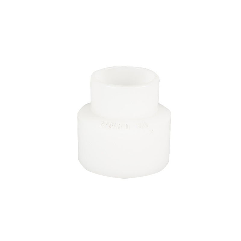
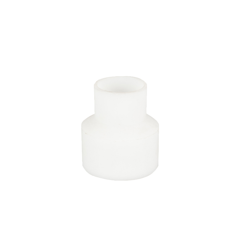
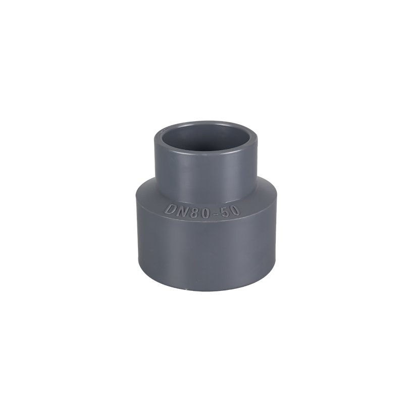
Plastic Pipe Fitting Reducers connect pipes or equipment interfaces with different diameters. One end has a larger flow passage, while the other end has a smaller passage. Depending on the direction of flow, the fitting may operate as a reducing transition or an expanding transition.
A diameter change affects velocity, turbulence, pressure loss, air accumulation and solids deposition. Reducer configuration, transition length, material and installation orientation should therefore be selected according to the complete operating condition rather than only the two nominal pipe sizes.
Ningbo Baodi Plastic Valve Co., Ltd. traces its origins to 1979, with Zhenhai Chemical Valve Factory and Beilun Plastic Valve Factory as its predecessors. Its long experience with industrial thermoplastic valves, pipes and fittings provides a practical basis for matching reducers with the chemical, pressure and temperature requirements of industrial piping systems.
Plastic Pipe Fitting Reducers
What Are Plastic Pipe Fitting Reducers?
Plastic Pipe Fitting Reducers are thermoplastic fittings used to connect two pipes or equipment interfaces with different diameters. The larger end connects to the larger pipe, while the smaller end connects to the reduced pipe or equipment nozzle.
Common materials include PVC, CPVC, PP and PVDF. Depending on the piping system, the ends may use solvent-cement sockets, socket fusion, butt fusion, threads or flanges.
Plastic Pipe Fitting Reducers may carry flow from the large end to the small end or from the small end to the large end. The fitting structure remains unchanged, but the hydraulic behavior differs in each direction.
Pipe-size transition: Reducers connect pipeline sections with different outside and inside diameters.
Equipment matching: They match a main pipeline with pump, valve, tank or filter connections.
Velocity adjustment: A diameter change increases or decreases the average flow velocity.
Compact installation: A molded reducer can replace several adapters and short pipe sections.
System modification: Reducers support equipment replacement and pipeline expansion where connection sizes have changed.
A pipe reducer is not a pressure-reducing valve. It changes the flow area but does not automatically maintain a stable downstream pressure. Pressure also depends on elevation, friction, pump operation, valves and downstream equipment.
Ningbo Baodi Plastic Valve Co., Ltd. manufactured its first plastic diaphragm valve in 1979. The product passed the technical appraisal of the Ministry of Chemical Industry in 1983. This early work with pressure-containing plastic components established experience that later supported the company’s expansion into industrial plastic pipes and fittings.
How a Plastic Reducer Changes Fluid Flow
Flow Area Change
The large and small ends of a reducer have different effective flow areas.
When fluid moves from the large end to the small end, the available area decreases. At the same flow rate, average velocity normally increases.
When fluid moves from the small end to the large end, average velocity decreases. This may create low-velocity regions behind the transition.
Static Pressure Change
A change in diameter affects local velocity and pressure distribution. However, final system pressure cannot be determined from the reducer dimensions alone.
Pipe friction, elevation, valves, pumps and process equipment must also be considered.
Turbulence and Energy Loss
Every diameter transition creates some local disturbance.
A short reducer or a sharp internal step generally creates more turbulence. A longer and smoother transition can reduce flow separation but requires more installation space.
Flow Direction
Large-to-small flow is normally described as reducing flow. Velocity rises and local friction may increase.
Small-to-large flow is an expansion condition. Velocity decreases, but rapid expansion can produce vortices and recirculation zones.
System Evaluation
Plastic Pipe Fitting Reducers are only one part of the piping network. Their effects should be assessed together with straight pipes, elbows, valves, pumps and filters.
Concentric and Eccentric Plastic Reducers
Concentric Reducers
A concentric reducer keeps the large and small pipe centerlines on the same axis.
Its symmetrical shape makes it suitable for vertical piping and many general industrial installations. It is also convenient for prefabricated pipe sections because the centerline does not shift.
In a horizontal liquid line, however, a concentric reducer may create a local high or low area where air or liquid can collect.
Eccentric Reducers
An eccentric reducer has offset centerlines. One side remains relatively flat while the opposite side forms the transition.
This structure is selected when the piping layout needs a continuous top or bottom line. It is frequently considered near pump suction connections, drainage lines and pipelines carrying suspended solids.
Flat Side Up
A flat-side-up installation can reduce the possibility of a high pocket forming at the top of a horizontal liquid line.
This arrangement may help limit air accumulation near a pump suction connection. The final orientation should still follow the approved piping design.
Flat Side Down
A flat-side-down arrangement can maintain a more continuous lower flow path.
It may be useful where complete drainage or solids transport is more important than removing trapped gas.
Reducer Structure Comparison
| Reducer Type |
Centerline |
Main Advantage |
Main Limitation |
Typical Application |
| Concentric reducer |
Same centerline |
Symmetrical and easy to prefabricate |
May create pockets in horizontal lines |
Vertical piping and general service |
| Eccentric reducer |
Offset centerline |
Helps control air or liquid pockets |
Orientation must be specified |
Pump suction and drainage lines |
| Stepped reducer |
Usually aligned |
Compact installation |
Greater local flow disturbance |
Space-limited small systems |
| Long-transition reducer |
Concentric or eccentric |
Smoother flow transition |
Requires more installation length |
Higher-flow process piping |
Ningbo Baodi Plastic Valve Co., Ltd. expanded its product line to industrial plastic pipes and fittings in 2006. The broader product coverage allows reducers to be coordinated with matching pipe dimensions, valves and connection methods.
Concentric Reducers in Vertical and Horizontal Pipelines
Vertical Installation
Concentric reducers are well suited to vertical pipe runs because the centerline remains continuous.
The weight of the pipe and contained fluid should still be supported independently. The smaller connection should not carry the full weight of a larger liquid-filled pipe above it.
Horizontal Installation
A concentric reducer can be used in a horizontal pipeline when the system remains fully flooded and the risk of gas accumulation is low.
For fluids containing solids, the lower transition area should be reviewed for possible sediment accumulation.
Equipment Connections
Concentric Plastic Pipe Fitting Reducers are suitable where valves, filters and equipment nozzles share the same centerline.
They should not be used to correct a difference in equipment height. Pipe supports and equipment positions should be adjusted instead.
Procurement Dimensions
B-end buyers should confirm the large-end size, small-end size, total length and center-to-end dimensions.
For prefabricated piping, a small difference in reducer length can shift the position of nearby valves or equipment connections.
Eccentric Reducers Near Pump Suction Lines
Why Pump Suction Piping Requires Attention
Pump suction conditions are sensitive to trapped air and unstable incoming flow.
An incorrectly oriented reducer may create a pocket where gas collects. This can contribute to noise, vibration and irregular pump operation.
Reducer Orientation
In a horizontal liquid suction line, the flat side is commonly positioned to avoid creating an unnecessary high point.
The exact orientation should follow the pump arrangement and approved piping drawing. The fitting should be marked before bonding or fusion begins.
Distance from the Pump
A reducer installed immediately beside the pump can affect the inlet velocity profile.
The required straight-pipe length depends on the pump design, upstream valves, elbows and operating flow.
Pipe Support
The pump nozzle should not carry the weight of the plastic pipe or reducer.
Plastic Pipe Fitting Reducers and adjacent pipes should be supported so pump vibration is not transferred directly into the connection.
Information Required from Buyers
Project buyers should provide the pump inlet size, main-pipe size, center elevation, flow direction and required eccentric orientation.
Providing only the two nominal diameters may not be enough for correct production.
Reducing Flow and Expanding Flow
Large-to-Small Flow
When fluid enters the large end and exits through the small end, average velocity increases.
High velocity can increase noise, vibration, friction and erosion. This is particularly important for abrasive particles and concentrated chemical streams.
The smaller downstream pipe should be sized for the actual flow rate rather than only the connected equipment nozzle.
Small-to-Large Flow
When fluid enters the small end, the reducer acts as an expansion fitting.
Velocity decreases, but a rapid expansion can create recirculation zones. Wastewater, fibres and suspended solids may settle in these slower areas.
Bidirectional Systems
Some circulation, backwash and cleaning systems operate in both directions.
Plastic Pipe Fitting Reducers used in these systems should be evaluated for both reducing and expanding flow. The normal production direction may not represent the most demanding operating condition.
Plastic Reducers and Other Size-Transition Methods
| Transition Method |
Main Advantage |
Main Limitation |
Typical Application |
| Molded plastic reducer |
Integrated and relatively smooth transition |
Fixed size combination |
Standard pipe-size changes |
| Reducing coupling |
Compact straight connection |
Usually has a shorter transition |
Small and medium pipe systems |
| Reducer bushing |
Fits inside a larger fitting |
May create a sharp internal step |
Compact auxiliary branches |
| Flanged reducer |
Removable connection |
Needs more space and fasteners |
Equipment and valve interfaces |
| Fabricated transition |
Can match special dimensions |
Requires additional quality control |
Large or non-standard systems |
A molded reducer provides a complete transition in one fitting. A reducing coupling is compact but normally creates a shorter change in diameter.
A reducer bushing saves space, although its internal step may increase turbulence. Several nested bushings also add connection points and should not be used without reviewing bore size and pressure loss.
A flanged reducer is suitable where dismantling is required. Fabricated transitions can match special dimensions but require careful inspection of joining quality and dimensional accuracy.
Materials for Plastic Pipe Fitting Reducers
PVC Reducers
PVC reducers are widely used in ambient-temperature water treatment and general chemical-transfer systems.
PVC has low weight and resistance to many acids, alkalis and salt solutions. Socket versions are commonly joined using compatible solvent-cement procedures.
The material has limitations at elevated temperature and with certain organic solvents.
CPVC Reducers
CPVC provides higher temperature capability than standard PVC in many applications.
It is used in selected hot-water and chemical-processing systems. Pipes, reducers, valves and joining materials should all be compatible with CPVC.
Ningbo Baodi Plastic Valve Co., Ltd. became one of the early domestic enterprises to apply CPVC in industrial-grade piping valves. This experience supports the selection of CPVC reducers as part of a coordinated thermoplastic system.
PP Reducers
PP is suitable for many acids, alkalis and industrial wastewater streams.
PP reducers may use socket fusion, butt fusion or flanged connections. Pressure capability should be checked at the actual service temperature.
PVDF Reducers
PVDF is used with aggressive chemicals and selected high-purity fluids.
It provides broad chemical resistance and useful temperature performance. Fusion cleanliness, material traceability and internal-surface quality are important considerations.
Material Comparison
| Parameter |
PVC |
CPVC |
PP |
PVDF |
| Temperature capability |
Moderate |
Higher than PVC |
Moderate |
Relatively high |
| Chemical resistance |
Suitable for many general chemicals |
Suitable for selected chemicals at elevated temperature |
Strong resistance to many acids and alkalis |
Broad resistance to aggressive chemicals |
| Common connection |
Solvent-cement socket |
Solvent-cement socket |
Fusion or flange |
Controlled fusion |
| Typical application |
Water treatment and chemical transfer |
Hot water and selected chemical lines |
Wastewater and acid-alkali systems |
High-purity and demanding chemical service |
| Main concern |
Temperature and solvent limits |
Complete CPVC compatibility |
Fusion quality and pressure derating |
Clean installation and cost |
Material selection should use the exact chemical, concentration, maximum temperature and pressure. General descriptions such as corrosive liquid do not provide enough information for industrial procurement.
Connection Types for Plastic Pipe Fitting Reducers
Socket Reducers
Socket reducers are common in PVC and CPVC piping.
The large and small sockets have different insertion dimensions, so both pipe ends should be measured and marked separately.
The reducer direction and orientation should be confirmed before the permanent connection is made.
Fusion Reducers
Fusion reducers are widely used in PP and PVDF systems.
The two ends may require different heating tools or clamping arrangements. During fusion, the reducer should remain aligned and supported.
Overheating can restrict the bore, while insufficient heating may produce an incomplete joint.
Threaded Reducers
Threaded reducers are mainly used in small instrument and auxiliary lines.
Thread size and form must match. Excessive tightening can crack the plastic around the smaller connection.
Flanged Reducers
Flanged reducers are useful for larger equipment connections and joints that require dismantling.
The large and small ends may use different bolt patterns, so each flange should be specified separately.
Connection Comparison
| Connection Type |
Main Advantage |
Main Limitation |
Typical Application |
| Socket |
Compact and convenient |
Normally permanent |
PVC and CPVC piping |
| Fusion |
Strong continuous joint |
Requires controlled installation tools |
PP and PVDF systems |
| Threaded |
Removable in smaller sizes |
Thread stress and leakage risk |
Instrument and auxiliary lines |
| Flanged |
Easy to dismantle |
Requires more space and fasteners |
Pumps, tanks and large valves |
Diameter Ratio, Transition Length and Internal Bore
Diameter Ratio
A large difference between the two ends creates a greater change in flow area.
A very large single-step reduction may increase velocity and local pressure loss. Some systems may benefit from a two-stage transition.
Transition Length
A longer transition normally creates a smoother change in velocity.
A short reducer saves space but may produce stronger turbulence. Selection should balance hydraulic performance with available installation length.
Internal Bore
The actual internal diameter affects flow velocity more directly than the nominal pipe size.
Different pipe-wall thicknesses can create an internal step even when the outside dimensions appear compatible.
Important Dimensional Data
Large-end size: Confirm the actual outside and inside diameters.
Small-end size: Confirm the matching pipe dimensions and wall series.
Socket depth: Check the required insertion length at both ends.
Total length: Verify that the reducer fits the available installation space.
Centerline offset: Eccentric reducers require a defined offset and flat-side orientation.
Ningbo Baodi Plastic Valve Co., Ltd. exports industrial thermoplastic products to more than 60 countries. Confirming drawings before production helps reduce dimensional incompatibility across different project standards.
Pressure Loss and Velocity Control
Plastic Pipe Fitting Reducers create local pressure loss because the fluid changes velocity through the transition.
The loss depends on the diameter ratio, transition length, internal surface and flow direction.
A reducer should not be treated as a zero-resistance component, particularly in systems containing several consecutive size changes.
Excessive small-end velocity can increase noise, vibration and erosion. In chemical applications, it may also increase wear at nearby bends and valves.
Expansion flow can create low-velocity regions where fibres, crystals or suspended solids settle.
Reducers installed near flowmeters, control valves or pump inlets should include suitable straight-pipe spacing where required by the system design.
Air Pockets, Liquid Traps and Installation Orientation
Air Accumulation
A local high point in a horizontal liquid pipeline can trap air.
A concentric reducer may create such a pocket in some layouts. Accumulated gas can affect pump suction and measurement stability.
Liquid Traps
A discontinuous lower pipe surface can retain liquid.
This is undesirable in systems that require complete drainage, frequent cleaning or chemical changeover.
Solids Deposition
Low-velocity areas can collect solids and sediment.
The orientation of eccentric Plastic Pipe Fitting Reducers should maintain a suitable lower flow path where solids transport is important.
Orientation Marking
The flat side of an eccentric reducer should be identified on the installation drawing and marked on the fitting before joining.
Relying only on field judgment can produce inconsistent installation across a project.
Maintenance Safety
Before dismantling, operators should confirm that pressure and liquid are not trapped inside the transition.
A reducer may retain process fluid even when the adjacent straight pipe appears drained.
Pipe Supports and External Loads
Plastic Pipe Fitting Reducers should have suitable support on both sides.
Large and small pipes may require different support spacing because their weight and stiffness differ.
Pumps, valves, filters and other equipment should have independent support. The reducer should not carry equipment weight.
Thermal movement should also be considered. A transition between different materials may experience different expansion on each side.
A reducer must not be used to correct pipe-center or angular errors. Forced alignment introduces bending stress into the fitting and its joints.
In vertical piping, the larger liquid-filled section should have separate load support instead of relying on the smaller reducer connection.
Installing Plastic Pipe Fitting Reducers
Confirm the Configuration
Before installation, confirm the large end, small end, flow direction and reducer type.
For eccentric reducers, mark the required flat-side orientation.
Inspect the Reducer
Check the fitting for cracks, deformation, contamination and damaged connection surfaces.
Confirm the material, dimensions, pressure rating and connection method.
Prepare the Pipes
Cut both pipe ends square and remove burrs, dust and plastic fragments.
Complete any chamfering, cleaning or heating preparation required by the joining method.
Connect the Large End
The large end may require more working space and larger tools.
Support the reducer during joining so the weight of the large pipe does not rotate or bend the fitting.
Connect the Small End
Mark the required insertion depth or fusion position.
Maintain the specified centerline or eccentric offset and prevent joining material from entering the bore.
Curing and Cooling
PVC and CPVC connections require adequate curing. PP and PVDF fusion joints require complete cooling.
The reducer should not be pressurized or loaded before both joints are ready.
Ningbo Baodi Plastic Valve Co., Ltd. has obtained ISO 9001, ISO 14001 and ISO 45001 certifications. Controlled manufacturing supports dimensional consistency, while correct field installation determines the final reliability of the connection.
Pressure Testing and Commissioning
Before testing, inspect the large and small joints, reducer orientation and support arrangement.
Confirm that solvent-cement joints have cured and fusion joints have cooled.
Fill the system slowly with an approved test liquid and release air from high points.
Increase pressure in controlled stages and check both reducer ends for leakage, movement and deformation.
During initial operation, compare pressure and flow before and after the reducer where practical.
Noise, vibration or unstable pump suction may indicate excessive velocity, poor orientation or an unsuitable upstream arrangement.
Common Problems with Plastic Pipe Fitting Reducers
Leakage at the Large End
Possible causes: Insufficient surface preparation, inadequate insertion, incomplete fusion or bending from an unsupported large pipe.
Leakage at the Small End
Possible causes: Size mismatch, poor alignment, thread overtightening or excessive downstream velocity.
Reducer Cracking
Possible causes: Forced alignment, restricted thermal expansion, unsupported equipment or unsuitable temperature conditions.
Excessive Noise
Possible causes: Excessive diameter ratio, high small-end velocity, internal steps or installation too close to a valve or pump.
Air Accumulation
Possible causes: An unsuitable concentric reducer in a horizontal liquid line, incorrect eccentric orientation or missing venting at a high point.
Solids Deposition
Possible causes: Reduced velocity after expansion, a discontinuous lower flow path or inadequate flushing.
Experience from industrial projects served by Ningbo Baodi Plastic Valve Co., Ltd. shows that repeated reducer problems often originate from system layout, support or flow conditions rather than the fitting body alone.
Purchasing Considerations for Industrial Buyers
Reducer Configuration
The purchase specification should state whether the reducer is concentric or eccentric.
The large-end and small-end dimensions should be listed separately. Eccentric reducers should include the required flat-side orientation.
Process Information
Buyers should provide the fluid, concentration, pressure, temperature and normal or maximum flow rate.
The presence of gas, solids, fibres or crystals should also be stated.
Dimensional Confirmation
Important data includes actual outside diameters, internal bores, socket depths, total length and centerline offset.
For prefabricated systems, dimensions should be confirmed through an approved drawing.
Connection Method
The order should identify socket, fusion, threaded or flanged ends.
The two ends may use different connection types when the reducer joins a pipeline to equipment.
Pressure and Temperature Data
The applicable pressure rating and temperature-derating information should be confirmed before ordering.
Products should not be selected only according to visible wall thickness or weight.
Batch Consistency
B-end buyers should check concentricity, eccentric offset, total length, interface dimensions and material identification across production batches.
Consistent dimensions are important for skid manufacturers, distributors and repeat projects.
Technical Documentation
Project requirements may include dimensional drawings, material data, inspection records and pressure-related documents.
These requirements should be agreed before production.
Packaging and Supply Coordination
Large and small ends should be protected from impact and deformation. Different materials and size combinations should be clearly identified.
Ningbo Baodi Plastic Valve Co., Ltd. offers broad industrial thermoplastic valve, pipe and fitting categories. Its exports to more than 60 countries and experience serving tens of thousands of enterprises support engineering contractors, project buyers and distributors requiring coordinated supply.
Inspection, Maintenance and Replacement
Routine inspection should cover the reducer body, both connections and nearby pipe supports.
Operators should check for leakage, cracking, discoloration, deformation and pipe movement.
Systems containing solids should be flushed according to the process requirements, with particular attention to low-velocity regions after an expansion.
Cleaning chemicals must be compatible with the reducer material and joining system.
Bonded or fusion Plastic Pipe Fitting Reducers with structural damage normally need to be cut out and replaced. External patching does not reliably restore pressure-containing strength.
Maintenance records should include the material, large and small dimensions, reducer type, orientation, flow direction, pressure and temperature.
Typical Applications of Plastic Pipe Fitting Reducers
Pump Suction and Discharge Lines
Reducers connect pump nozzles with larger process pipelines.
Suction-side applications require careful attention to eccentric orientation and air-pocket prevention.
Water Treatment Systems
Plastic Pipe Fitting Reducers connect different sizes in filtration, dosing, backwash and circulation pipelines.
Chemical Processing
Reducers connect tanks, reactors, filters and transfer pipelines with different capacities.
Material compatibility and flow velocity are major considerations.
Wastewater Systems
Reducers connect collection and discharge pipelines of different sizes.
Internal transitions should reduce sediment accumulation and support effective flushing.
Tank Connections
Reducers match storage-tank nozzles with main pipelines.
Pipe loads should not be transferred into the tank connection.
Process Skids
Compact reducers connect equipment and main lines inside limited frames.
Dimensional accuracy is especially important for prefabricated installation.
Frequently Asked Questions About Plastic Pipe Fitting Reducers
What Are Plastic Pipe Fitting Reducers Used For?
They connect plastic pipes, valves and equipment interfaces with different diameters.
Is a Pipe Reducer a Pressure-Reducing Device?
No. It changes the pipe diameter and flow velocity but does not regulate pressure like a control valve.
What Is the Difference Between a Concentric and Eccentric Reducer?
A concentric reducer keeps both pipe centerlines aligned. An eccentric reducer offsets the centerlines and provides one relatively flat side.
Which Reducer Is Suitable for a Pump Suction Line?
A horizontal liquid suction line often requires evaluation of an eccentric reducer to reduce air-pocket risk. The final orientation should follow the approved piping design.
Can a Reducer Be Installed in Either Flow Direction?
Many reducers can carry flow in either direction, but reducing and expanding flow create different hydraulic conditions.
Do Plastic Pipe Fitting Reducers Cause Pressure Loss?
Yes. The amount depends on the diameter ratio, transition length, flow direction and internal geometry.
Can Different Plastic Materials Be Connected?
Incompatible materials should not be bonded or fused directly. A designed transition connection should be used.
Why Does a Reducer Create Noise?
Possible causes include excessive velocity, a large one-step diameter change, an internal restriction or installation close to a disturbed flow source.
Can a Reducer Bushing Replace a Full Reducer?
It may be suitable for small, low-flow applications. High-flow or solids-containing systems may require a smoother full-body reducer.
Should Plastic Reducers Be Supported?
Yes. Both connected pipes and nearby equipment should be supported so the reducer does not carry excessive weight or bending load.
Can a Cracked Plastic Reducer Be Repaired?
A cracked pressure-containing reducer should normally be removed and replaced. External adhesive does not restore its original structural performance.
What Information Should Buyers Provide Before Ordering?
Buyers should provide the material, fluid, concentration, pressure, temperature, flow rate, large-end size, small-end size, concentric or eccentric structure, connection method, installation orientation, quantity, packaging and technical-document requirements.