Engineering Deep Dive: Actuated Ball Valves vs Manual Ball Valves
Understanding the operational dynamics of fluid control systems is critical for pipeline longevity, system reliability, and overall process safety. Plant engineers and system designers constantly evaluate the transition from standard manual ball valves to automated solutions based on line pressures, cycling frequencies, and environmental safety factors. This comprehensive analysis details the mechanical differences, financial metrics, and operational protocols directly from the precision manufacturing perspective.
Mechanical Anatomy and Fluid Control Dynamics
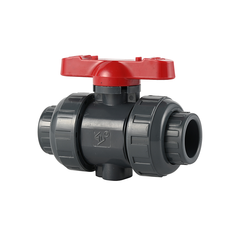
The fundamental architecture of a manual ball valve relies on a quarter-turn spherical disc to regulate fluid. The operator directly manipulates the flow path by rotating an external lever or gear handle, which realigns or blocks the internal ported sphere. This direct mechanical linkage ensures immediate tactile feedback and high reliability in remote field applications where electrical grids or compressed air infrastructure are entirely unavailable.
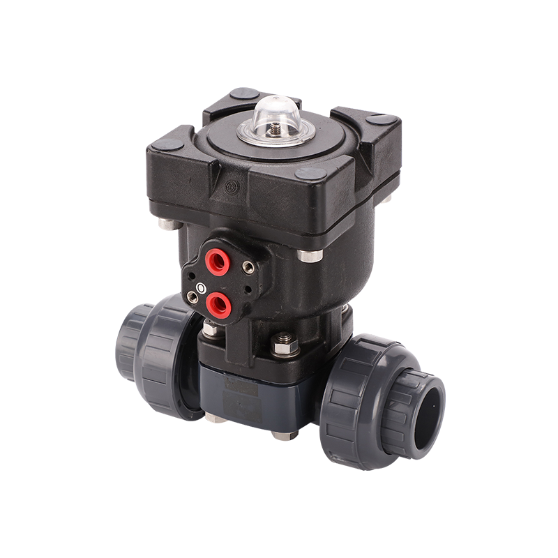
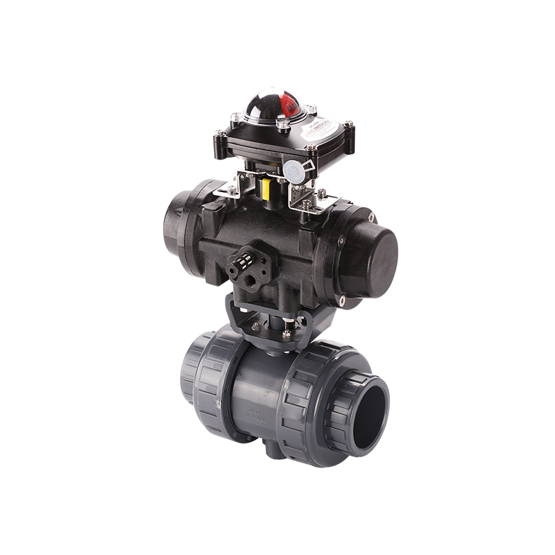
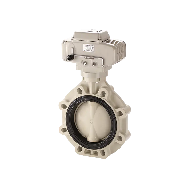
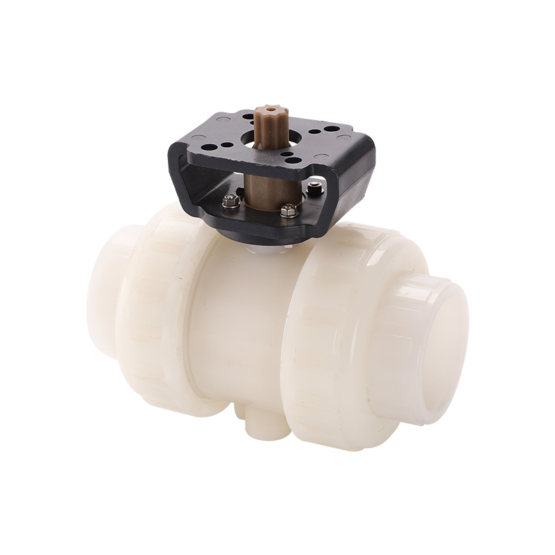
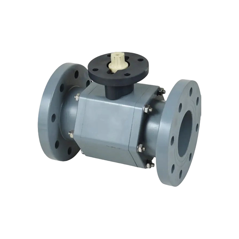
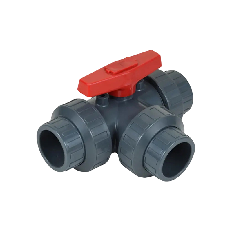
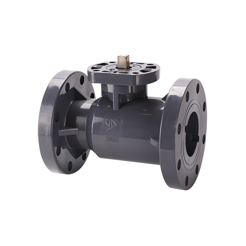
When fluid diversion, multi-port blending, or complex bypass loops are integrated into a compact piping footprint, a 3 way manual ball valve serves as a highly efficient mechanical solution. Utilizing engineered T-port or L-port internal sphere configurations, operators can safely divert flow to alternate pipelines or mix separate media streams without installing multiple inline isolation units. Conversely, automated systems replace the manual handle with high-torque pneumatic cylinders or electric motors. While a traditional ball valve manual setup is optimized for low-frequency isolation, actuated ball valves become necessary for high-cycle processes, emergency shutdown protocols (ESD), and large-diameter pipelines where localized fluid torque exceeds human physical capabilities.
Technical Specification Matrix
| Engineering Metric |
Manual Ball Valve |
Actuated Ball Valves |
| Power Source Requirements |
Physical manual force (direct lever or mechanical gear reducer) |
Compressed utility air (2-8 bar pneumatic) or source voltage (AC/DC electric) |
| Actuation Speed Response |
Variable, depending entirely on human reaction and physical leverage |
Rapid and constant (calibrated in milliseconds to seconds to prevent water hammer) |
| Torque Management |
Limited by operator limits; requires heavy gearboxes for sizes above DN150 |
High continuous output limits; easily masters extreme pressure differentials |
| System Integration |
Standalone physical operation; requires onsite visual position verification |
Fully compatible with automated DCS, PLC, and SCADA control networks |
Total Cost of Ownership (TCO) Analysis
While initial procurement budgets frequently drive short-term component selection, analyzing the Total Cost of Ownership across a standard multi-year operational lifecycle reveals the true engineering value of each configuration.
| Evaluation Metric |
Manual Ball Valve Configuration |
Automated Actuator Systems |
| Initial Capital Investment |
Highly cost-effective. Consists solely of the mechanical valve body, stem assembly, and handle. |
Higher initial cost due to supplementary electronic/pneumatic drives, solenoids, and positioners. |
| Operational Labor Costs |
Continuous long-term expense. Requires direct deployment of maintenance teams to physically operate lines. |
Virtually zero labor cost. Executes command signals instantly from a centralized control room. |
| Maintenance Predictability |
Reactive methodology. Relies heavily on routine manual checks to catch packing wear or line leaks. |
Proactive diagnostics. Smart positioners track seat wear variables to flag maintenance needs early. |
Material Customization for Extreme Environments
Adapting the underlying metallurgy and elastomeric seals to precise fluid compositions is standard manufacturing practice. General industrial setups often utilize stainless steel (ASTM A351 CF8M) or cast carbon steel (ASTM A216 WCB) bodies paired with reinforced PTFE seats for non-corrosive water, gas, or refined oil lines. However, for abrasive mining slurries, aggressive chemical processing, or extreme thermal applications, metal-to-metal seating configurations and specialized superalloys like Duplex stainless steel, Hastelloy, or Monel are engineered directly at our factory. This targeted material science strategy prevents premature body erosion and structural seal blowout, guaranteeing a stable pressure boundary whether utilizing a robust automated setup or a standard manual ball valve.
Factory-Level Quality Assurance and Hydrostatic Testing
Every flow control assembly must undergo strict physical validation before installation in municipal or industrial processing plants. Advanced manufacturing facilities subject each specialized 3 way manual ball valve and inline automated valve to multi-stage hydrostatic and pneumatic pressure evaluations. By executing high-pressure shell and seat testing up to 1.5 times the maximum designed pressure rating, manufacturers ensure casting density and absolute zero-leakage performance across dynamic seals. This rigorous testing regimen guarantees that regardless of whether project engineers deploy manual handles for auxiliary lines or automated setups for high-stakes process loops, the pressure containment boundary remains perfectly secure.
Critical Troubleshooting and Maintenance Protocols
Preserving tight sealing integrity over extended lifecycles requires adherence to systematic maintenance protocols specific to the chosen actuation method.
- Stem Packing Nut Field Adjustments: On a standard manual ball valve, periodic compression of the stem gland nut compensates for normal wear in high-cycle operations. If the lever becomes increasingly stiff during standard quarter-turn operation, do not use excessive mechanical extensions; instead, clear the pipeline and check for particle or sediment accumulation near the internal sphere.
- Pneumatic Air Supply Inspection: Pneumatic actuators require clean, dry, and regulated air feeds. Contaminated or overly humid supply lines allow moisture into the cylinder, leading to internal spring degradation, cylinder seal tearing, and significantly slowed response times during safety cutoffs.
- Fail-Safe Mechanical Override Verification: For automated lines handling hazardous or volatile chemicals, verify that the integrated manual override handwheels are checked and cycled every quarter. This ensures operating engineers can immediately regain physical process control during complete power grid or pneumatic air plant dropouts.