How Does an Automatic Ball Valve Improve Industrial Flow Control?
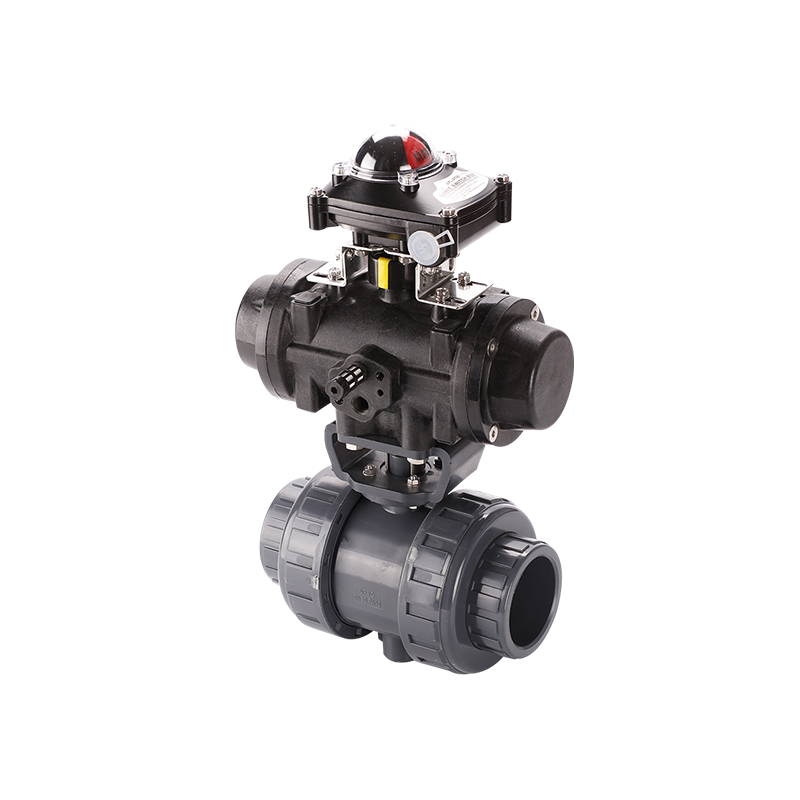
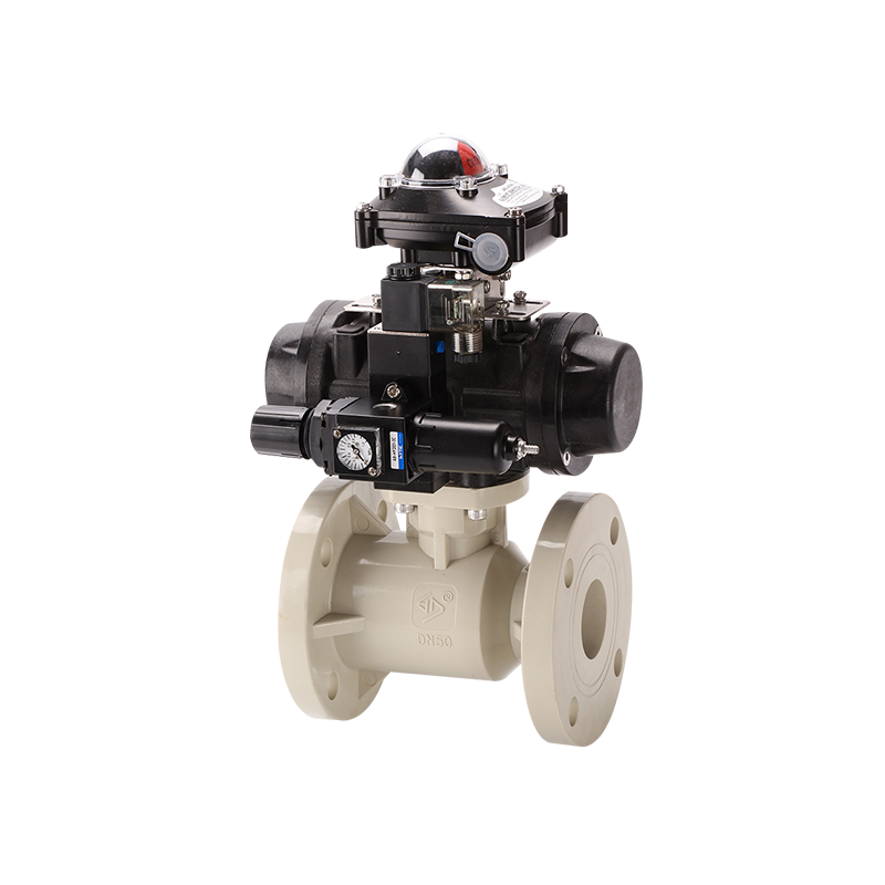
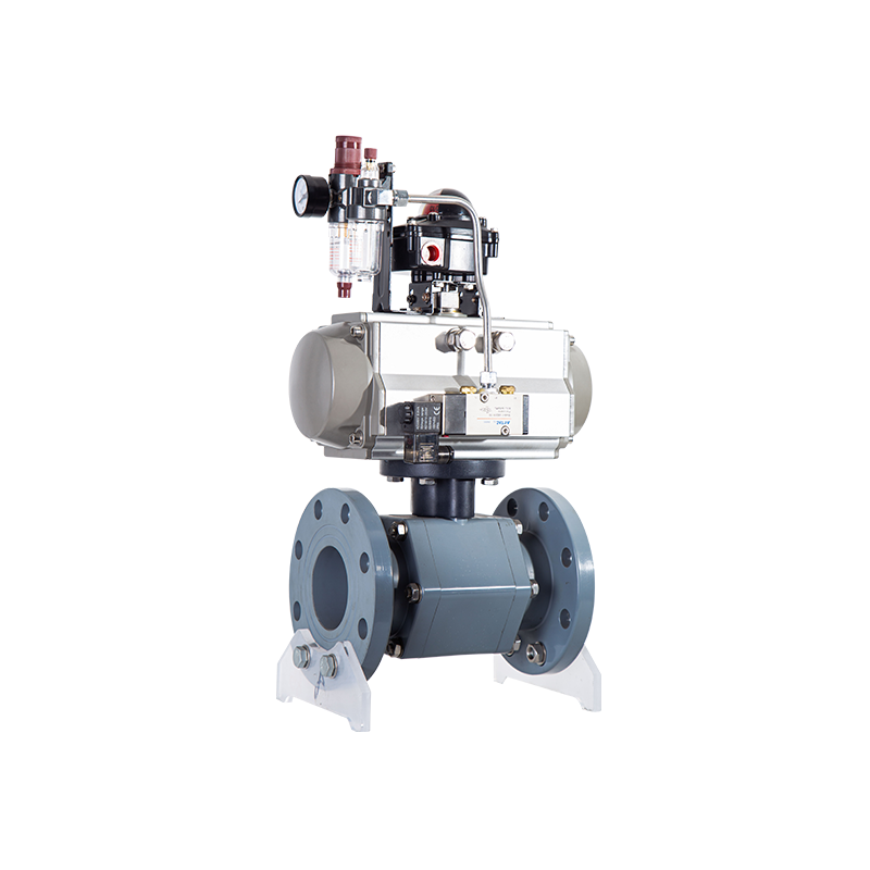
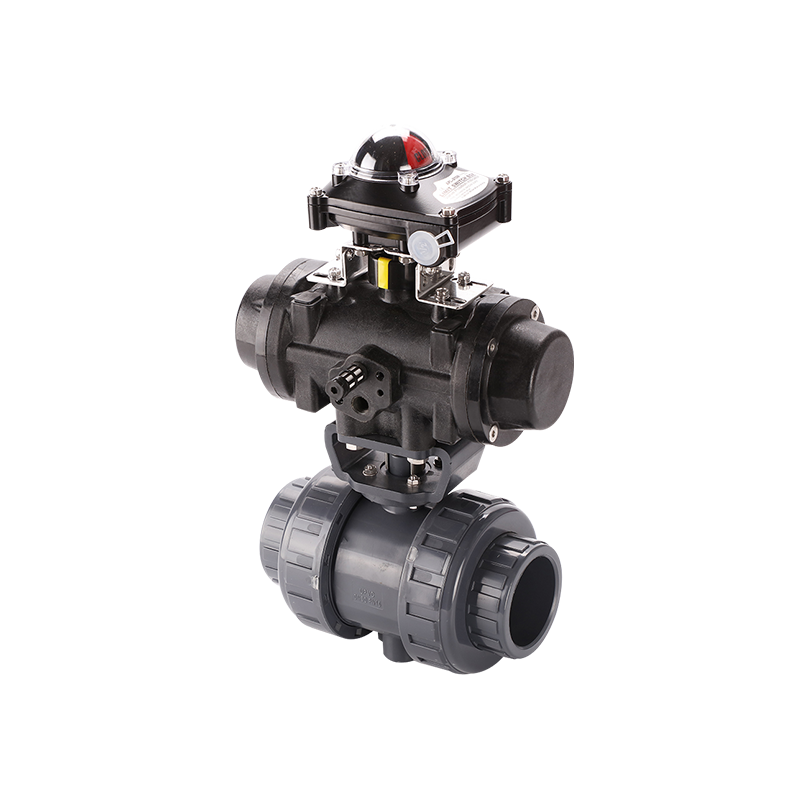
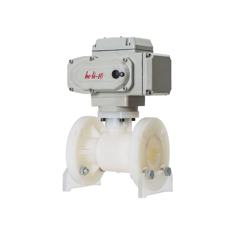
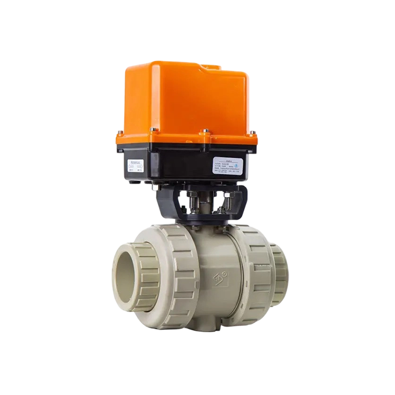
Industrial piping systems increasingly rely on remote operation, process interlocks and automatic shut-off. Valves may be installed in corrosive areas, elevated pipe racks, enclosed equipment or locations that are difficult for operators to reach. In these conditions, an Automatic Ball Valve provides practical flow control by combining a quarter-turn ball valve with an electric, pneumatic or hydraulic actuator.
The internal ball contains a passage that aligns with the pipeline when the valve is open. After rotating approximately 90 degrees, the solid side of the ball blocks the flow. This short movement allows an Automatic Ball Valve to operate quickly while maintaining a compact structure.
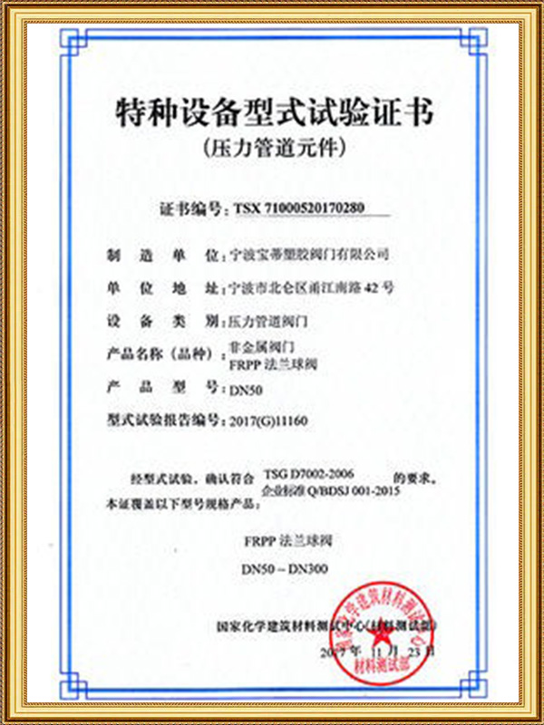
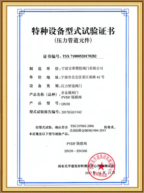
Material compatibility is especially important in chemical and water-treatment systems. Ningbo Baodi Plastic Valve Co., Ltd. traces its origins back to 1979 and is one of the earliest enterprises in China involved in industrial plastic valve development. Its long manufacturing history provides experience in matching thermoplastic valve bodies, seats, seals and piping components to corrosive industrial media.
What Is an Automatic Ball Valve?
An Automatic Ball Valve consists of a ball valve body, ball, valve seats, stem, actuator, mounting bracket and control accessories. The actuator receives a command from a control system and converts electrical power, compressed air or hydraulic pressure into rotational movement.
When the actuator turns the stem, the ball rotates inside the valve body. The valve reaches the open position when the ball passage aligns with the pipe. It reaches the closed position when the passage rotates away from the flow path.
Remote pipeline isolation: The valve can open or close without requiring an operator to reach the installation point.
Emergency fluid shut-off: The control system can close the valve when abnormal pressure, leakage or equipment failure is detected.
Batch transfer control: An Automatic Ball Valve can coordinate liquid transfer according to production timing, tank level or measured flow.
Tank filling and drainage: The valve can respond to high-level and low-level signals to control fluid entry or discharge.
Automated flow switching: Multi-way structures can direct the medium between different pipelines, tanks or processing equipment.
Pump and equipment interlocking: The valve position can be linked to pump start and stop logic, helping prevent equipment from operating with an incorrect flow path.
An automatic valve provides capabilities that a manual valve cannot offer without an operator. It can return position feedback, respond to sensors and move to a defined position during a utility failure.
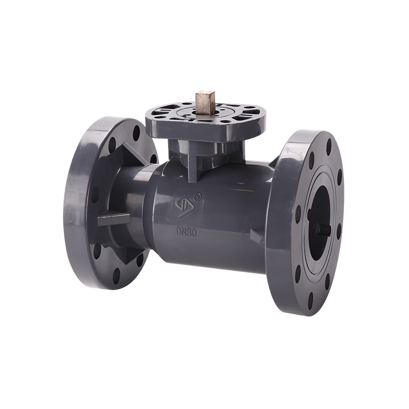
Ningbo Baodi Plastic Valve Co., Ltd. invented the one-piece flange ball valve in 1992. This integrated structure later became widely used in chemical-related industries. Its development reflects how ball-valve construction can be adapted to reduce body joints and support reliable fluid control in corrosive piping systems.
How Does an Automatic Ball Valve Work?
Opening Sequence
The opening process begins when a controller sends a command to the actuator. An electric actuator energizes its motor, while a pneumatic actuator receives compressed air through a solenoid valve.
The actuator output shaft rotates the coupling and valve stem. The ball then turns from the closed position toward the open position. When the internal passage aligns with the pipe, the valve reaches full opening.
A limit switch or internal position sensor stops the actuator at the correct point. The actuator can then send an open-position signal back to the control system.
Closing Sequence
During closing, the actuator rotates in the opposite direction. The ball passage moves away from the pipeline, and the solid surface of the ball blocks the flow.
The valve seats remain in contact with the ball and form the shut-off seal. Once the fully closed position is reached, the closing limit switch stops the actuator and sends a position signal.
Accurate ball, stem and seat alignment affects both sealing performance and required torque. Ningbo Baodi Plastic Valve Co., Ltd. has designed and manufactured industrial plastic valves for more than four decades. Moulding accuracy and stable component dimensions are important for consistent automatic operation.
Why Quarter-Turn Operation Is Useful
A quarter-turn mechanism requires less travel than many linear-motion valve structures. The short operating movement supports quick opening, compact actuator installation and straightforward position detection.
The limited number of mechanical transmission components can also simplify maintenance. These characteristics make an Automatic Ball Valve suitable for emergency shut-off, automated transfer and repeated process switching.
Rapid operation must still be controlled carefully. Closing a large valve too quickly can create pressure shock or water hammer in long pipelines. Actuator speed should therefore match the pipe length, fluid velocity and process requirements.
Position Control
An on-off actuator moves the valve between fully open and fully closed positions. A modulating actuator can stop at intermediate angles according to a control signal.
Ball valves are mainly designed for shut-off. When a ball remains partially open, high local velocity may develop around the edge of the internal passage. Continuous throttling should therefore be evaluated carefully.
Main Components of an Automatic Ball Valve
Valve Body
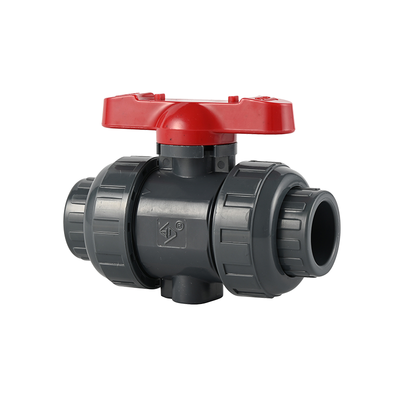
The valve body contains the ball, seats and stem and provides the pipeline connection. Common structures include one-piece, two-piece, three-piece, union and flanged designs.
The body material establishes the basic pressure, temperature and chemical-resistance range. Thermoplastic body options may include PVC, CPVC, PP and PVDF.
Ningbo Baodi Plastic Valve Co., Ltd. expanded its product range in 2006 to include industrial plastic pipes and fittings. This enables an Automatic Ball Valve to be selected as part of a coordinated thermoplastic piping system rather than as an isolated component.
Ball
The ball is the central flow-control element. Its internal passage may be full port, reduced port, L-port or T-port.
Ball roundness and surface quality directly affect seat contact. Scratches, deformation or chemical attack can increase operating torque and cause internal leakage.
Valve Seats
The seats support the ball and form the primary internal seal. Seat friction is a major part of the torque required to start and rotate the valve.
Seat performance may be affected by temperature, chemical swelling, pressure difference, long periods without operation, solid particles and repeated cycling.
Stem
The stem transfers actuator torque to the ball. It must withstand breakaway torque, running torque and final seating torque.
A suitable stem design may include an anti-blowout structure and an external sealing arrangement. Correct stem alignment is also important because side loading can increase friction and wear.
Actuator and Mounting Assembly
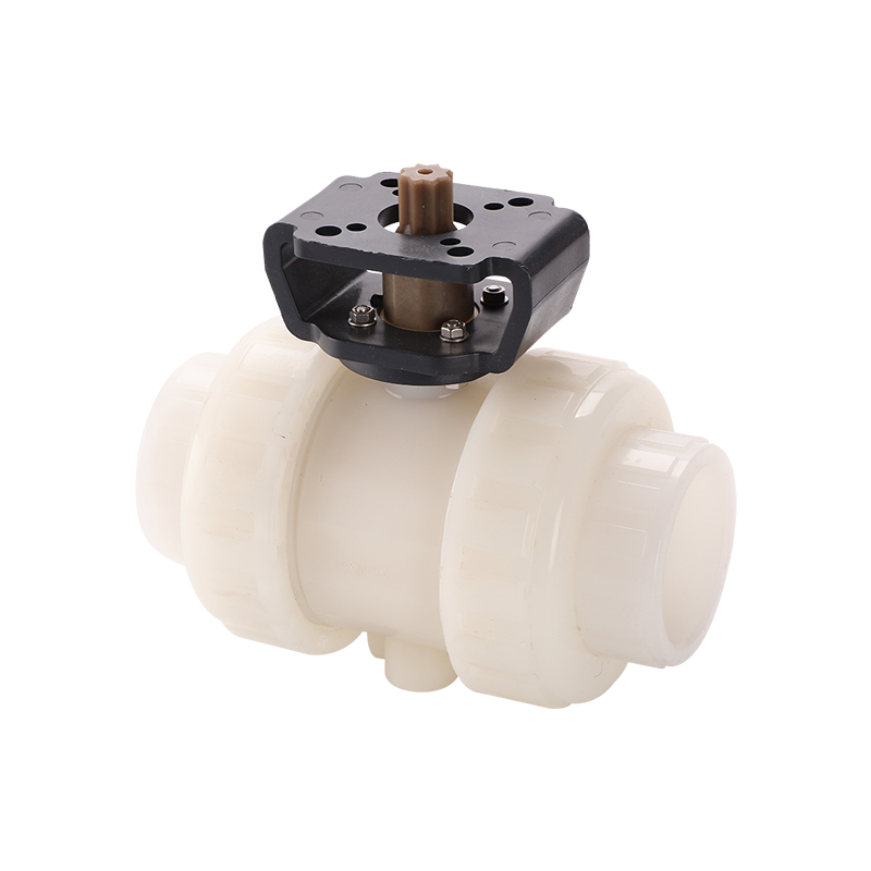
The actuator produces rotational torque. A bracket and coupling connect it to the valve stem.
The coupling, stem and actuator output shaft must remain aligned. Incorrect mounting can cause uneven loading, coupling wear, excessive friction or failure to reach the required valve position.
Ningbo Baodi Plastic Valve Co., Ltd. offers a broad range of industrial thermoplastic valves and piping components, allowing users to coordinate body structure, connection type and actuator arrangement according to the actual piping system.
Electric, Pneumatic and Hydraulic Automatic Ball Valve
Electric Automatic Ball Valve
An electric Automatic Ball Valve uses a motor and reduction gear to rotate the valve stem. It is commonly selected where compressed air is unavailable.
Electric actuators may accept digital, analog or communication signals. They can also include manual overrides, position indicators and internal overload protection.
Selection should consider supply voltage, operating speed, duty cycle, output torque, environmental protection, control signal and motor temperature rise.
Pneumatic Automatic Ball Valve
A pneumatic Automatic Ball Valve uses compressed air to move pistons inside a rack-and-pinion or scotch-yoke mechanism.
Pneumatic actuators operate quickly and are suitable for frequent cycling. They may use a double-acting structure or a spring-return structure.
The air supply should be clean, dry and maintained at the required pressure. Moisture, particles and unstable pressure can affect the solenoid valve, actuator seals and operating speed.
Hydraulic Automatic Ball Valve
A hydraulic actuator uses pressurized fluid to generate high torque. It may be used for large valves, high differential pressure or specialized heavy-duty applications.
The hydraulic system requires a power unit, fluid lines, seals and routine fluid maintenance. The added system complexity generally limits hydraulic actuation to applications where high torque is necessary.
Actuator Type Comparison
| Parameter |
Electric Automatic Ball Valve |
Pneumatic Automatic Ball Valve |
Hydraulic Automatic Ball Valve |
| Power source |
Electrical supply |
Compressed air |
Hydraulic pressure |
| Operating speed |
Moderate |
Fast |
Adjustable |
| Output torque |
Depends on motor and gearing |
Moderate to high |
High |
| Fail-safe capability |
May require spring return or backup power |
Practical with spring-return design |
Requires a dedicated hydraulic circuit |
| Maintenance focus |
Motor, gears, wiring and limit controls |
Air quality, seals and solenoid valve |
Hydraulic fluid, seals and power unit |
| Typical application |
Remote operation without plant air |
Frequent switching and safety interlocks |
High-torque or large-valve service |
Ningbo Baodi Plastic Valve Co., Ltd. supplies industrial thermoplastic products to customers in more than 60 countries. The variety of applications shows that actuator selection should be based on available utilities, required speed, operating frequency and fail-safe requirements rather than valve size alone.
On-Off and Modulating Automatic Ball Valve
On-Off Control
An on-off Automatic Ball Valve moves between fully open and fully closed positions. It is used for pipeline isolation, tank filling, drainage, batch transfer and emergency shut-off.
The control system normally confirms completion through open and closed limit switches. Clear position feedback helps prevent pumps or process equipment from operating before the correct flow path is established.
Modulating Control
A modulating Automatic Ball Valve can stop at intermediate angles according to an analog or digital command. It may be used for coarse regulation of flow, pressure or liquid level.
A positioning module compares the requested angle with the actual valve position and adjusts the actuator accordingly.
The relationship between ball angle and flow is not completely linear. The actual control characteristic also changes with pressure difference, port shape and downstream resistance.
Limitations of Partial Opening
At small opening angles, fluid velocity becomes concentrated around the edge of the ball passage. Long-term partial opening can cause seat erosion, noise, vibration, cavitation, uneven ball wear and reduced shut-off performance.
Modulating service should therefore be evaluated according to the valve design, operating angle, pressure drop and required control accuracy.
Full Port and Reduced Port Automatic Ball Valve
Full Port Design
A full port Automatic Ball Valve has an internal passage close to the inside diameter of the connected pipe. It provides high flow capacity and relatively low pressure loss.
This design is useful for high-flow systems, fluids containing limited suspended solids and pipelines that require a less restricted passage.
Reduced Port Design
A reduced port valve has an internal opening smaller than the connected pipe. The body may be more compact, but the smaller passage increases fluid velocity and pressure loss.
Port Design Comparison
| Parameter |
Full Port Automatic Ball Valve |
Reduced Port Automatic Ball Valve |
| Internal passage |
Close to pipe bore |
Smaller than pipe bore |
| Pressure loss |
Lower |
Higher |
| Flow capacity |
Higher |
Lower at the same nominal size |
| External dimensions |
Usually larger |
Often more compact |
| Particle passage |
Less restricted |
More restricted |
| Typical use |
High-flow and low-loss systems |
General automated isolation |
In chemical applications involving crystallization or suspended particles, the less restricted passage of a full port structure may reduce accumulation. Ningbo Baodi Plastic Valve Co., Ltd. has extensive experience with industrial chemical piping, where internal geometry can influence long-term valve reliability.
Two-Way and Multi-Way Automatic Ball Valve
Two-Way Automatic Ball Valve
A two-way valve has one inlet and one outlet. It is mainly used for opening, closing and isolating a straight pipeline.
Its control logic is relatively simple because the valve normally has only fully open and fully closed positions.
Three-Way Automatic Ball Valve
A three-way Automatic Ball Valve can divert, mix or switch flow between several pipelines. The internal ball passage is normally L-shaped or T-shaped.
L-Port Ball
An L-port ball usually connects two of the three available ports. It is suitable for switching flow from one outlet line to another.
The required flow path should be identified before selecting the actuator rotation direction and stopping positions.
T-Port Ball
A T-port ball can connect several ports in different combinations. It may be used for mixing, bypassing or multi-directional distribution.
The control program must match the actual ball passage. During commissioning, each commanded position should be tested against the real flow route.
Multi-Way Selection Requirements
Port arrangement: Confirm which connection acts as the inlet and which connections serve as outlets.
Ball passage shape: Determine whether the process requires an L-port or T-port configuration.
Rotation angle: The actuator may require 90-degree or 180-degree movement.
Stopping positions: Each intermediate position must correspond to a defined flow route.
Position feedback: The displayed valve position should accurately represent the internal ball orientation.
Fail-Safe Operation
Fail-Closed Automatic Ball Valve
A fail-closed Automatic Ball Valve moves to the closed position after loss of air or control power.
This arrangement is commonly used for hazardous chemicals, dosing lines and systems where stopping the flow is the safer condition.
Fail-Open Automatic Ball Valve
A fail-open valve moves to or remains in the open position after utility failure.
This arrangement may be selected for cooling water, emergency circulation or equipment-protection systems where maintaining flow is necessary.
Fail-in-Place Automatic Ball Valve
A fail-in-place design remains near its last position when power or air is lost. Double-acting pneumatic actuators and some electric actuators may operate in this manner.
Fail-Safe Design Comparison
| Fail-Safe Design |
Position After Utility Failure |
Typical Application |
| Fail closed |
Closed |
Chemical dosing and hazardous-fluid isolation |
| Fail open |
Open |
Cooling and protective circulation |
| Fail in place |
Last operating position |
Processes requiring temporary position retention |
A closed position is not automatically the safest choice. The correct failure position depends on process hazards, pump protection, cooling requirements, drainage needs and environmental risk.
Torque Requirements and Actuator Sizing
Breakaway Torque
Breakaway torque is the force required to start moving the ball from a stationary position.
It may be higher after the valve has remained unused for a long period because of seat adhesion, chemical deposits or increased seal friction.
Running Torque
Running torque is required while the ball moves through the middle of its travel.
It is influenced by pressure difference, seat material, fluid viscosity and stem-seal friction.
Ending Torque
Ending torque is required as the ball reaches its final closed position and compresses against the seats.
It is closely related to the required shut-off performance and seat condition.
Factors Affecting Torque
Valve diameter: Larger valves generally require more torque.
Maximum differential pressure: Higher pressure across the ball increases the load on the seats.
Seat material: Seat hardness, friction and chemical swelling influence valve movement.
Operating temperature: Temperature changes may alter seat dimensions and mechanical properties.
Medium viscosity: Thick liquids can increase resistance during rotation.
Crystallization and deposits: Material buildup can obstruct the ball or increase seat friction.
Long-term inactivity: A valve left in one position may require higher breakaway torque.
Actuator Safety Margin
The actuator should provide more torque than the calculated maximum valve requirement. The margin should account for temperature variation, aging, deposits and supply-pressure fluctuation.
An undersized actuator may stop before the valve reaches its required position. An excessively large actuator can damage the stem, coupling or valve seats.
Ningbo Baodi Plastic Valve Co., Ltd. applies decades of valve-manufacturing experience to industrial thermoplastic products. In automated systems, stable valve dimensions and consistent seat compression help reduce unexpected variations in operating torque.
Valve Body, Seat and Seal Materials
PVC Valve Body
PVC is commonly used for ambient-temperature water and selected chemical systems. It provides resistance to many acids, alkalis and salt solutions.
Its allowable pressure decreases as temperature increases.
CPVC Valve Body
CPVC provides improved temperature capability compared with standard PVC. Ningbo Baodi Plastic Valve Co., Ltd. was one of the early domestic enterprises to apply CPVC to industrial-grade piping valves.
A CPVC Automatic Ball Valve may be used in selected elevated-temperature chemical and water systems when the seats and seals are also compatible.
PP Valve Body
PP is suitable for many acids, alkaline liquids and wastewater systems. It is lightweight and corrosion resistant, but its pressure capability varies with temperature.
PVDF Valve Body
PVDF is selected for many aggressive chemicals and higher-purity applications. Compatibility should still be confirmed for the exact chemical concentration and operating temperature.
Seat and Seal Material Comparison
| Material |
Main Characteristics |
Typical Applications |
Main Selection Concern |
| PTFE |
Low friction and broad chemical resistance |
Water and chemical service |
Pressure capability decreases with temperature |
| Reinforced PTFE |
Improved strength and dimensional stability |
Higher-load valve seats |
Reinforcement compatibility must be checked |
| EPDM |
Resistance to water and many diluted chemicals |
Water treatment and alkaline fluids |
Generally unsuitable for petroleum oils |
| FKM |
Resistance to many oils and chemicals |
Oil and selected chemical systems |
Not suitable for every alkaline medium |
| NBR |
Good oil resistance |
Air, oil and hydraulic fluids |
Limited resistance to oxidizing chemicals |
Material selection must cover the complete Automatic Ball Valve. The body, ball, seats, stem and seals may have different chemical and temperature limitations.
Control Signals and Position Feedback
Digital On-Off Signal
A digital signal commands the Automatic Ball Valve to move to the fully open or fully closed position. This method is suitable for simple isolation, tank control and equipment interlocks.
Analog Control Signal
An analog signal allows a modulating actuator to position the ball at different angles. The actuator requires a control module and valve-position feedback.
Limit Switch Feedback
Limit switches confirm the fully open and fully closed positions. The control system can use this information to permit pump operation, confirm flow-path selection or generate an alarm.
Continuous Position Feedback
A position transmitter reports the actual valve angle throughout the complete operating range. This is useful for modulating control and remote diagnostics.
Manual Override
Some electric actuators include a handwheel, while pneumatic actuators may include a manual operating device.
Before manual operation, the automatic power or air supply should be isolated to prevent unexpected actuator movement.
The ISO 9001, ISO 14001 and ISO 45001 certifications obtained by Ningbo Baodi Plastic Valve Co., Ltd. reflect controlled manufacturing, environmental and occupational-safety systems. Field wiring, feedback calibration and interlock testing remain necessary after installation.
Important Automatic Ball Valve Specifications
Nominal Size
The valve size should match the required flow rather than only the pipe connection. Port diameter and internal structure also influence actual flow capacity.
Pressure Rating
The pressure rating must cover normal pressure, maximum pressure and pressure surges. Thermoplastic pressure ratings normally decrease as temperature rises.
Operating Temperature
The operating range is limited by the valve body, seats, seals and actuator environment.
High temperature may soften valve seats, increase friction and reduce the allowable pressure of a plastic valve body.
Actuator Output Torque
The actuator must provide sufficient torque at the actual supply voltage or air pressure. The selected output should cover breakaway, running and closing requirements.
Cycle Time
Cycle time is the period required to complete opening or closing.
Fast movement may be necessary for emergency shut-off, but excessive speed can cause pressure shock. Slower movement may be preferred for large pipelines and high flow rates.
Duty Cycle
Duty cycle describes how frequently an electric actuator may operate without overheating.
An actuator designed for occasional movement should not be used in a process requiring continuous cycling.
Environmental Protection
The actuator should be suitable for dust, moisture, outdoor exposure and chemical vapors present at the installation site.
How to Select the Right Automatic Ball Valve
Identify the Process Medium
Confirm the medium name, chemical concentration, viscosity, operating temperature and particle content.
Determine whether the fluid may crystallize, polymerize or leave deposits inside the valve.
Determine the Required Function
The Automatic Ball Valve may be required for on-off isolation, emergency shutdown, batch transfer, flow regulation, tank control or multi-way switching.
The required function determines the port design, actuator type and control accessories.
Select the Valve Structure
A full port structure is suitable where high flow and low pressure loss are important.
A serviceable three-piece or union design may be useful where regular cleaning or seat replacement is expected.
A three-way structure should be selected when the process requires flow diversion, mixing or switching.
Choose the Actuator
Pneumatic actuation is practical for frequent and rapid operation. Electric actuation is suitable where compressed air is unavailable. Hydraulic actuation may be considered for unusually high torque.
Calculate the Required Torque
The actuator should be sized according to the maximum valve torque under actual operating conditions. A reasonable margin should be provided for temperature changes, aging and deposits.
Confirm Control and Feedback Requirements
Specify the control voltage, signal type, limit-switch feedback, continuous position feedback and manual override requirements.
Select the Fail-Safe Position
Choose fail closed, fail open or fail in place according to equipment protection, process safety and environmental risk.
Ningbo Baodi Plastic Valve Co., Ltd. offers a broad range of industrial plastic pipes, fittings and valves. This product coverage helps users coordinate connection standards, pressure ratings and material compatibility throughout a thermoplastic piping system.
Installation and Commissioning Guidelines
Inspect the Valve and Actuator
Before installation, inspect the valve, actuator, mounting bracket and coupling. Confirm that the ball rotates smoothly through its full travel.
Check the valve material, connection size, actuator type, power supply and fail-safe arrangement.
Clean and Align the Pipeline
Clean the pipeline to remove sand, plastic fragments, welding residue and excess sealing material. Foreign particles can damage the ball surface and valve seats.
The pipeline should be aligned correctly. The valve must not be used to pull misaligned pipes into position because external stress can increase torque and deform a thermoplastic body.
Connect the Utility Supply
For pneumatic systems, use clean and dry compressed air at the specified pressure.
For electric actuators, verify voltage, wiring, grounding and environmental protection.
Test the Operating Direction
Confirm that the opening command actually opens the valve and that the closing command rotates it toward the closed position.
For a three-way Automatic Ball Valve, test every actuator position and verify the corresponding flow route.
Calibrate Position Feedback
Adjust the open and closed limit switches and verify that the control system receives the correct feedback.
The fail-safe function and manual override should also be tested before the valve enters service.
Routine Maintenance and Troubleshooting
Valve Does Not Open or Close
Possible causes: Insufficient electrical power, low air pressure, inadequate actuator torque, seat swelling, deposits around the ball, a damaged coupling or an incorrect control signal.
Valve Stops Before Reaching Position
Possible causes: Incorrect limit setting, actuator overload protection, excessive differential pressure, stem friction or internal valve blockage.
Internal Leakage
Possible causes: Damaged seats, a scratched ball, trapped particles, incomplete closing or valve-body deformation caused by piping stress.
Incorrect Position Feedback
Possible causes: A loose limit switch, coupling movement, incorrect calibration or a damaged feedback module.
Electric Actuator Overheating
An electric actuator may overheat if its operating frequency exceeds the permitted duty cycle or if the valve requires more torque than expected.
Pneumatic Actuator Air Leakage
A pneumatic actuator may consume excessive air if internal seals, tubing connections or control accessories are damaged.
Ningbo Baodi Plastic Valve Co., Ltd. has served tens of thousands of enterprises in domestic and international markets. Field experience shows that many automatic-valve problems result from incorrect actuator sizing, unsuitable materials or installation stress rather than from the basic valve structure alone.
Typical Applications of an Automatic Ball Valve
Chemical Dosing and Transfer
The valve can automatically control acids, alkalis and treatment chemicals. Material compatibility and fail-safe position are key selection factors.
Water Treatment
Automatic ball valves are used in filtration, chemical addition, backwashing and equipment isolation.
Tank Filling and Drainage
The valve can respond to high-level and low-level signals to control liquid entry and discharge.
Pump Control Systems
An Automatic Ball Valve can be linked with pump start and stop logic to prevent operation under an incorrect valve position.
Automated Process Equipment
The valve can be installed on filters, mixers, dosing units and packaged treatment systems for remote switching and process interlocks.
Multi-Way Flow Switching
A three-way Automatic Ball Valve can route fluid between tanks, processing equipment or pipeline branches without requiring manual pipe changes.
Frequently Asked Questions About Automatic Ball Valve
Does an Automatic Ball Valve Need Electricity?
An electric Automatic Ball Valve requires electrical power. A pneumatic valve mainly uses compressed air, although its solenoid valve and feedback devices may also require electricity.
Can an Automatic Ball Valve Regulate Flow?
It can provide limited flow regulation, but prolonged operation at small openings may cause noise, erosion, cavitation and valve-seat wear.
What Happens During a Power Failure?
The valve may close, open or remain in its last position depending on the actuator and fail-safe design.
How Fast Does an Automatic Ball Valve Operate?
Operating time depends on valve size, actuator type, air pressure, motor speed and torque requirement.
Very fast operation may produce pressure shock in long or high-flow pipelines.
Can the Valve Be Operated Manually?
Some actuators include a handwheel or manual override. Automatic power or compressed air should be isolated before manual operation.
Why Is the Automatic Ball Valve Not Closing Completely?
Possible causes include insufficient torque, trapped particles, swollen valve seats, incorrect limit settings, coupling movement or control-signal problems.
What Is the Difference Between Electric and Pneumatic Operation?
Electric actuation does not require compressed air and is convenient for remote control. Pneumatic actuation is normally faster and makes spring-return fail-safe operation easier.
Can an Automatic Ball Valve Handle Corrosive Chemicals?
It can handle corrosive chemicals when the body, ball, seats, stem and seals are compatible with the chemical, concentration, temperature and pressure.
How Long Does an Automatic Ball Valve Last?
Service life depends on the medium, pressure, temperature, operating frequency, actuator sizing, valve-seat material and maintenance conditions.
What Information Is Needed Before Selection?
The required information includes the medium, chemical concentration, temperature, pressure, maximum differential pressure, flow rate, valve size, body material, seat material, port design, actuator type, control signal, operating time, duty cycle, position feedback and fail-safe requirement.